3D Computer Graphics: Theory and Application I, Post 3
|
This is my third post relating to course 5SD045, it details the results of a field visit to Gotland Museum during 2014-09-16 and of a practical assignment to optimize topology given to us during the lecture of 2014-09-17, constituting the third week of the course. The visit to the museum was part of the second course turn-in, during which we will model and implement a game-ready 3d asset, modeled after a real-life object. The objective of the visit was to present us with real-life object suitable for the assignment; at the end of the visit we were informed that we were to select one of the objects the museum had on display and take as many reference photos as we felt necessary. Preferably what we felt necessary would be one shot for every 90 degree angle (if possible), as well as some additional shots for texture and detail reference. You can read about what object I chose a bit further down in this post, in addition to seeing the first step of the assignment. Before that, I’ll cover the practical assignment. The assignment was to optimize the topology of our colleagues meshes. We were divided into groups of three, and given a chart of how we were to share our meshes with the colleagues assigned to our group. We would then optimize their meshes (in this case with the focus on reducing the complexity of the mesh), and have our own optimized. At the end of the lecture we were instructed to go through the meshes internally and have the optimizer discuss the changes he/she saw fit to make with the author of the mesh. Finally a note before I post the images as well as list of changes I made / saw others make; the instructions specified that we were to name our colleagues but I think it keeps the tone neutral were I instead to call them Colleague A, B and C. I myself was B, their real names are available on the course portal. I had a bit of difficulty with how exactly I was to present this next assignment. Following the instructions I ended up with no less than a 700-word list/change-log type of document and 50 pictures illustrating the changes. To interject a bit of “ass armor” this list was written as I was making changes in the 3d suite so some of the entries might be a bit cryptic, but the images should straighten things out. To keep things flowing smoothly I’ve broken up each mesh/asset into its own set, and I’ll present first the pictures and the changes, along with a little blurb summing up the problems the assets had and any additional comments I might have. Legend; White = New, Grey = Old Set 1 – Colleague A Crate 2
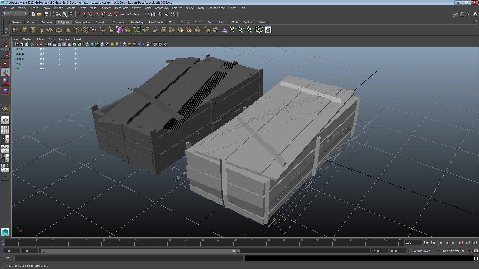
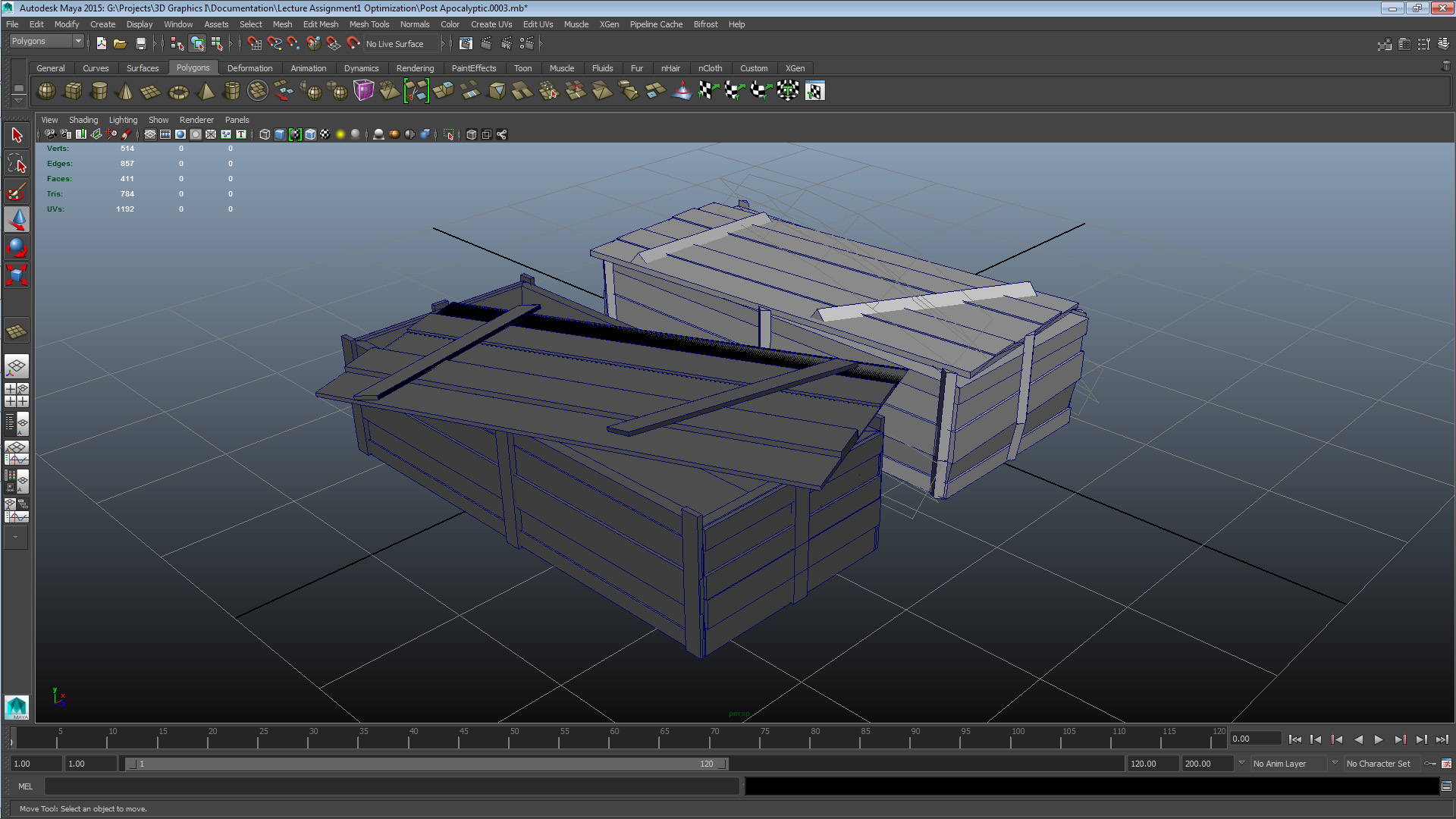
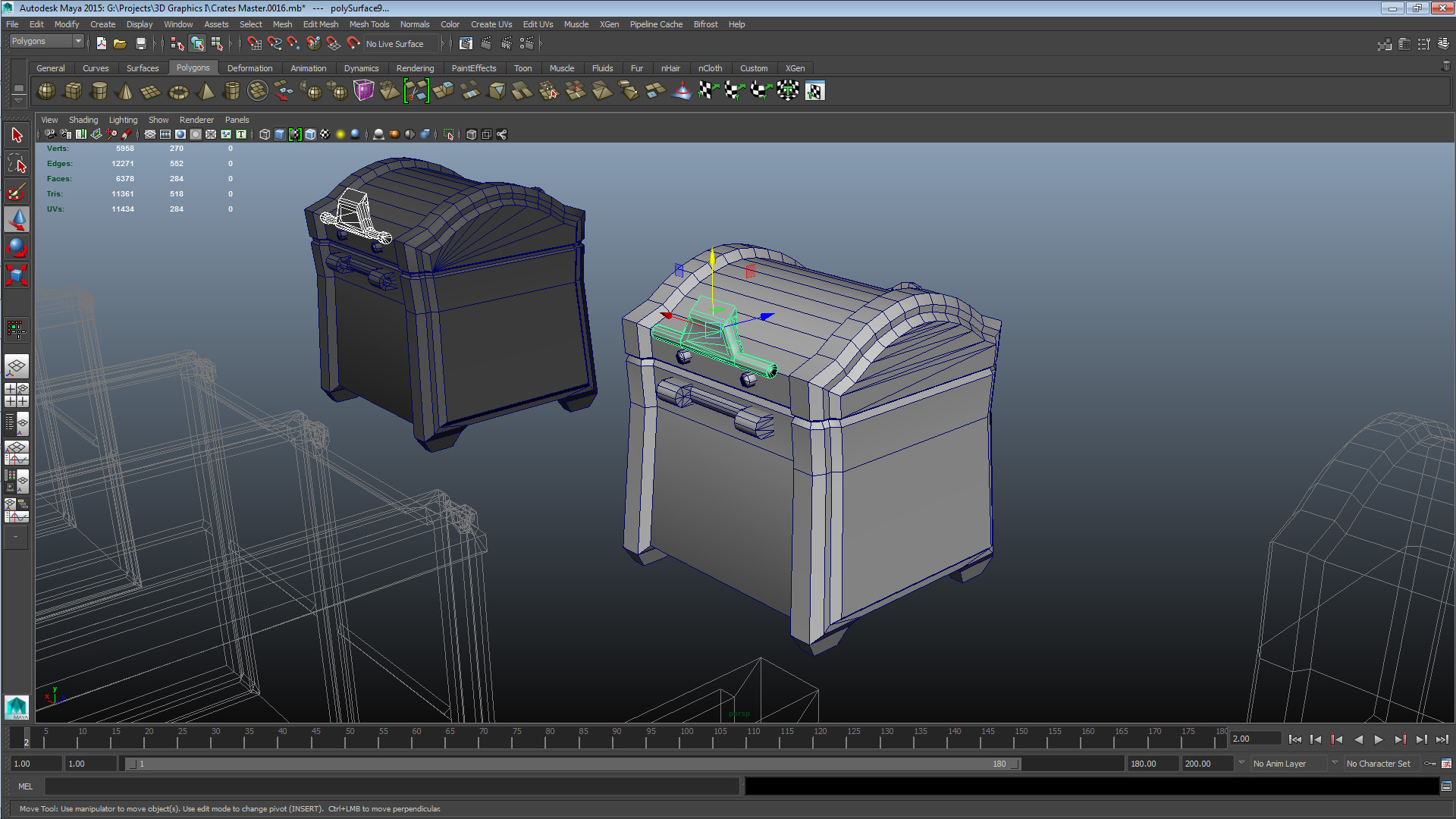
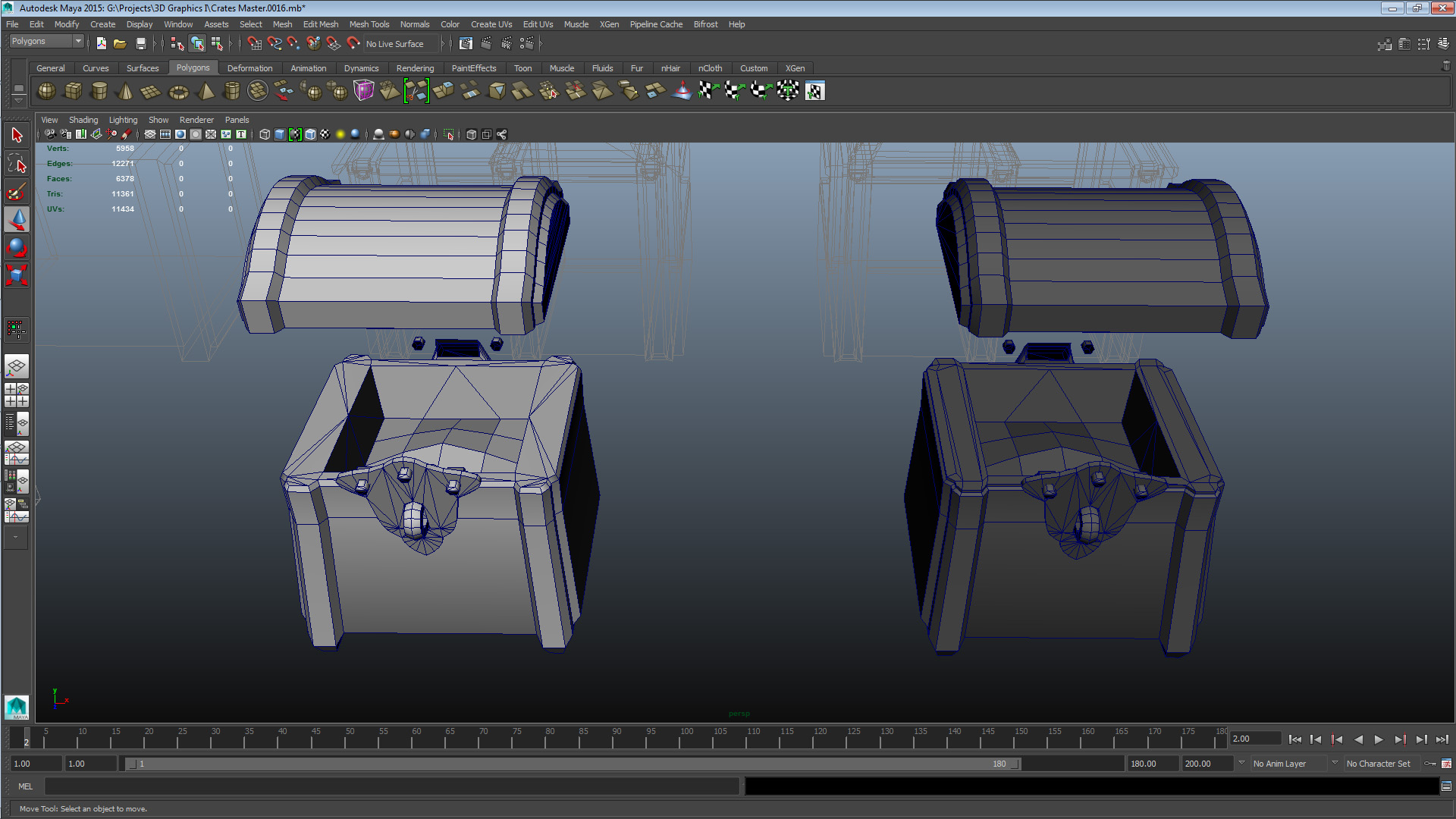
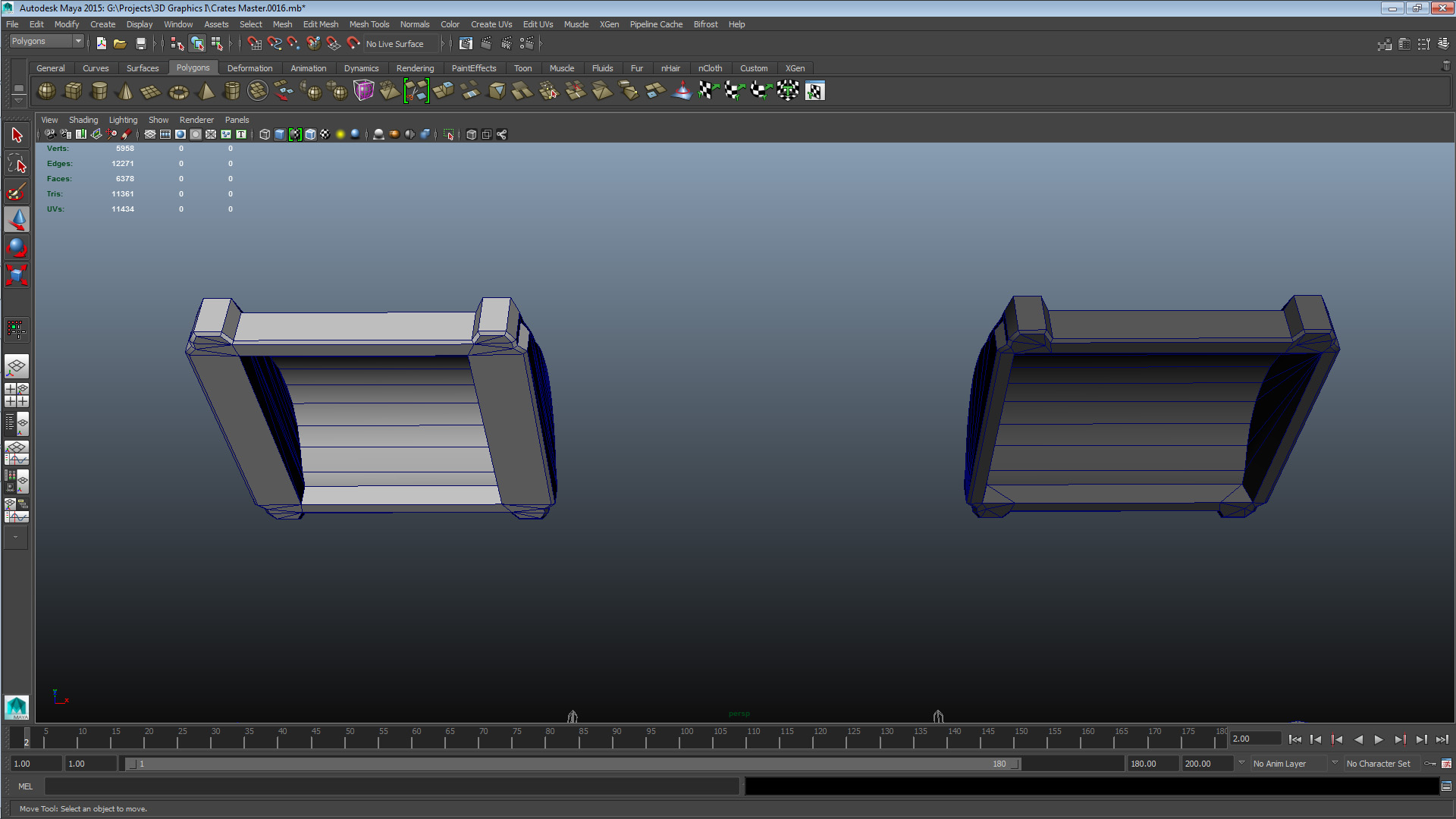
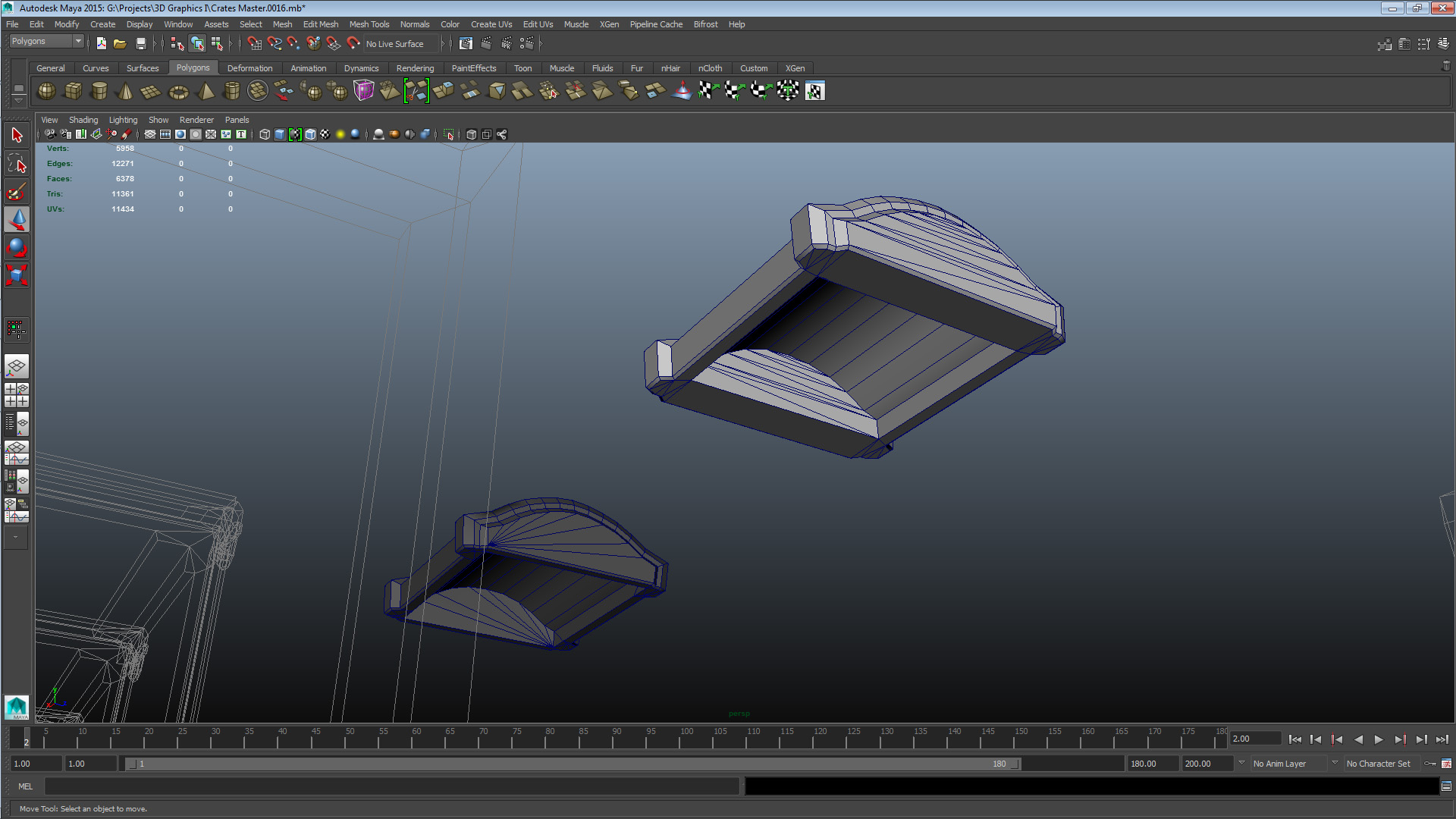
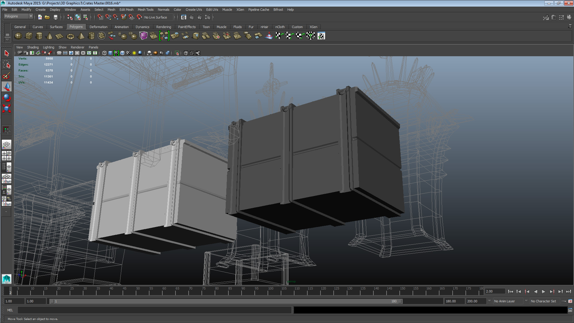
SET 1 CRATE COLLEAGUE A – CRATE 2 UNOPT: V 274 E 454 F 220 TRI 440 CRATE COLLEAGUE A – CRATE 2 OPT: V 150 E 271 F 143 TRI 248 The issues this mesh had were construction-related and mostly caused by messy extrudes. In addition it had some conceptual issues. The elements of the crate body exterior are all essentially full rectangular primitives, which I felt was inefficient, therefore I tessellated them to be a more worthwhile use of vertices. A lot of the thematic burden was on the lid element, so I toned it down by reducing its tilt and yaw, and distance from the box. The crate short edges had full primitives acting as individually modeled “planks”, which I decided was inefficient so I replaced them with extrudes along the chest exterior – an element I felt better conveyed the theme and style. I invested the geometry I freed up in increasing the detail of the vertical supports and reducing their overlap with the new extrudes. Finally I also made the choice to remove the crate interior as I felt it was no longer a worthwhile addition to the mesh with the altered position of the lid. When returning the mesh to the authoring colleague, I gave the suggestion that when rotating and modifying elements in more angles than one, the component editor can be a great way of keeping yourself completely informed about the precise positioning of your vertices. Also worth mentioning is that the majority of the optimization I did to this crate happened after the lecture, the reason for that is that the next crate I’ll cover ate up a lot of my time during the lecture because of its complexity. Set 2 – Colleague C Crate 2
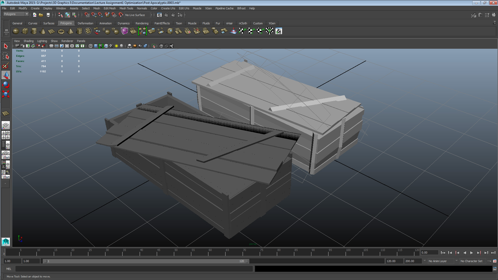
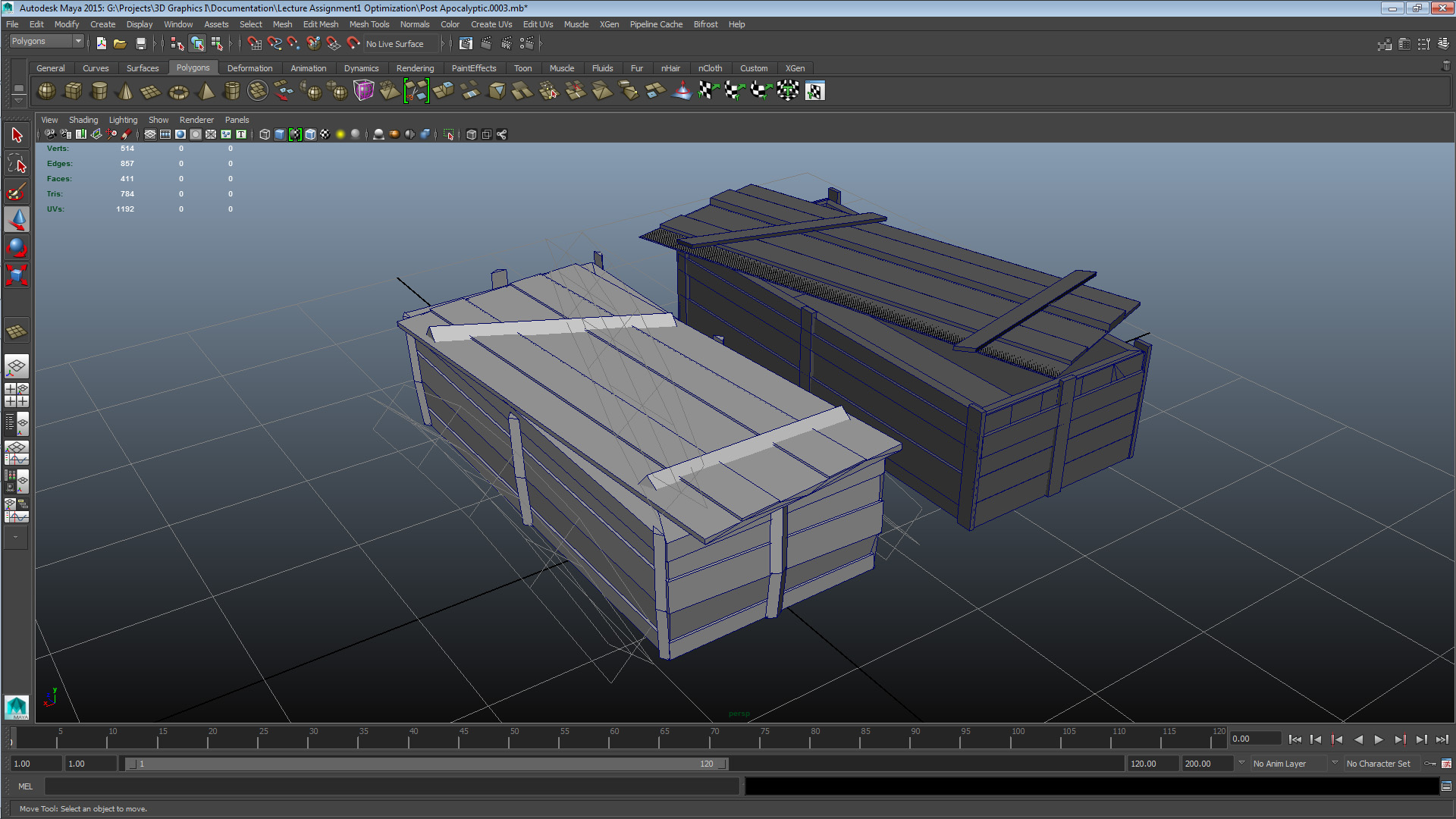
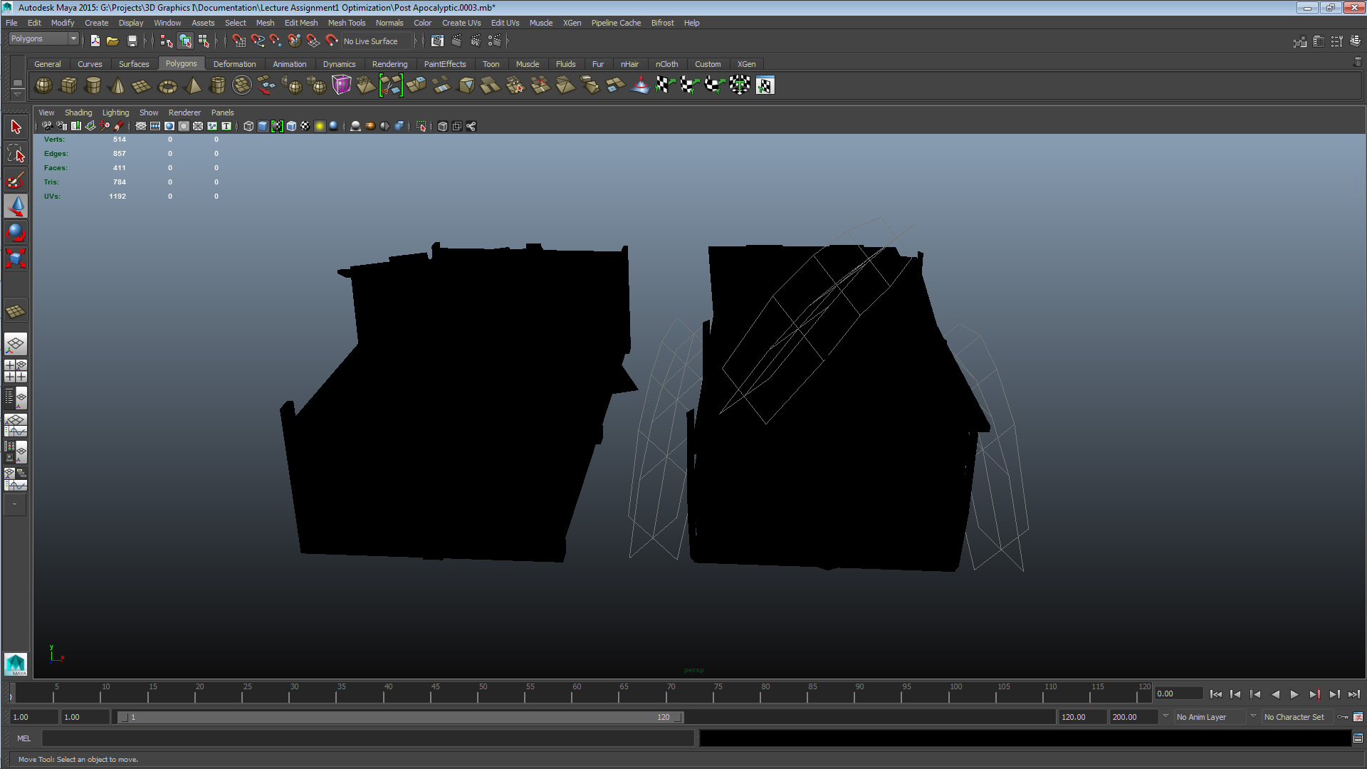
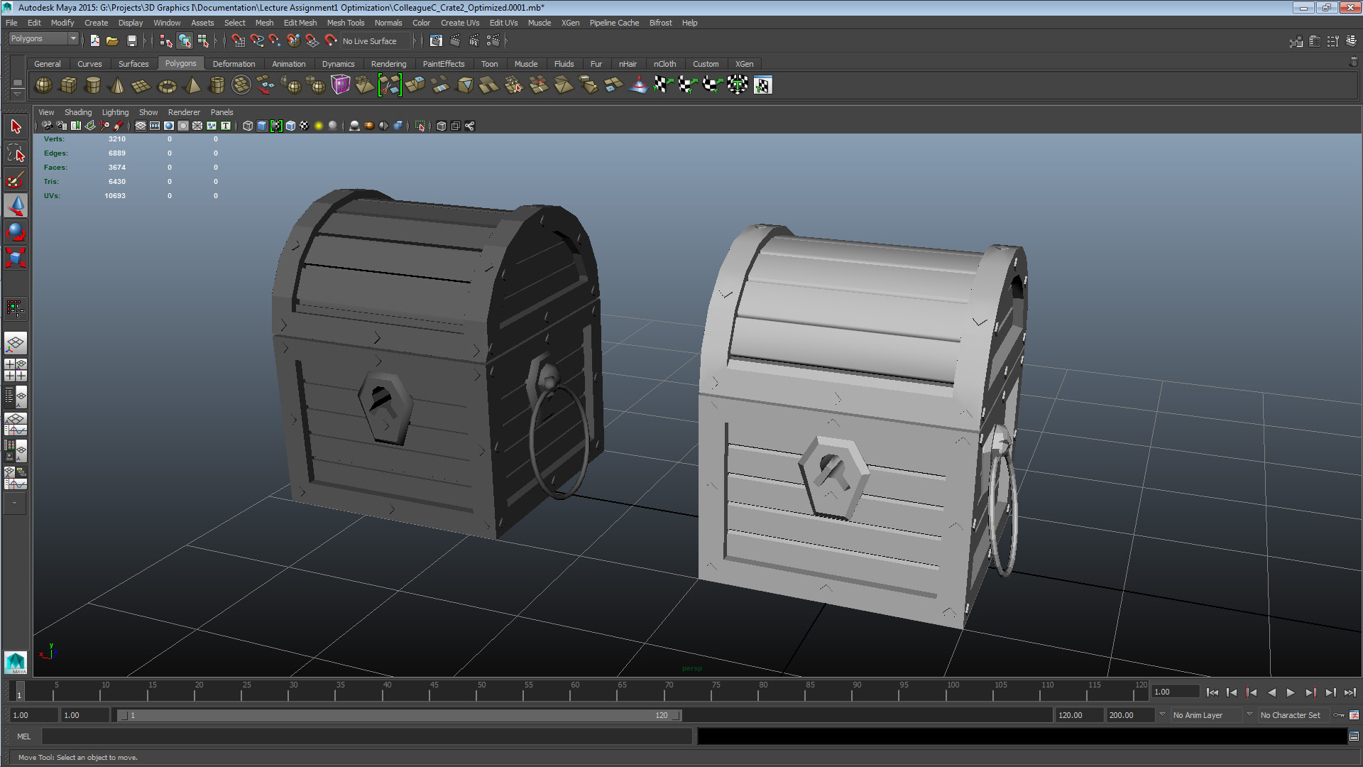
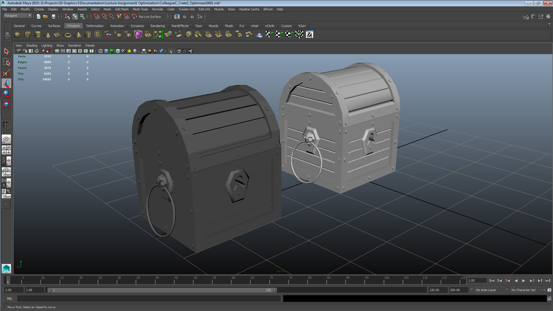
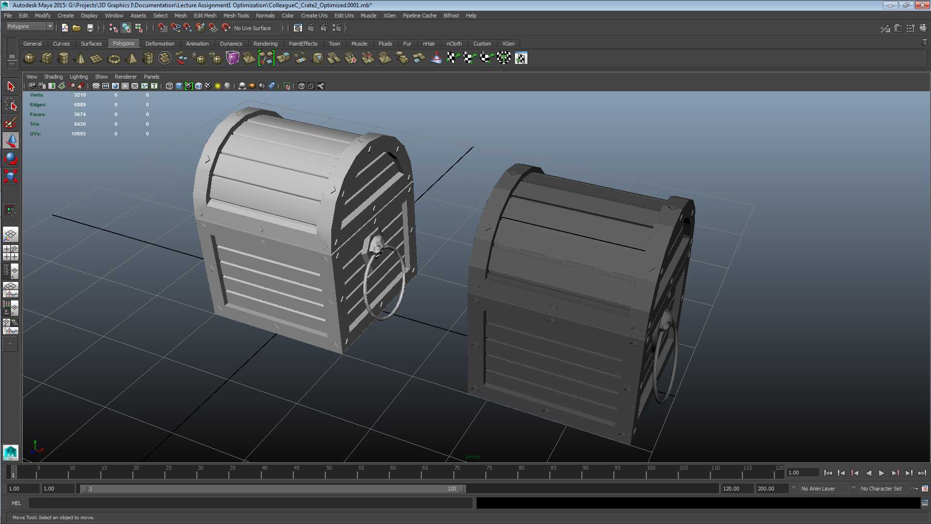
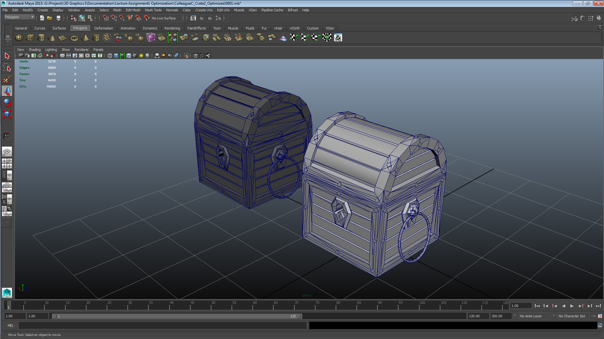
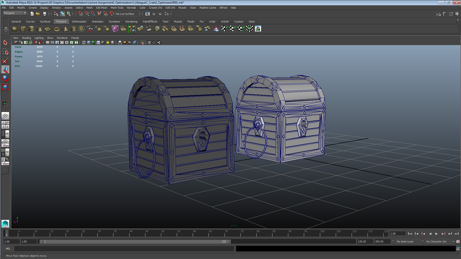
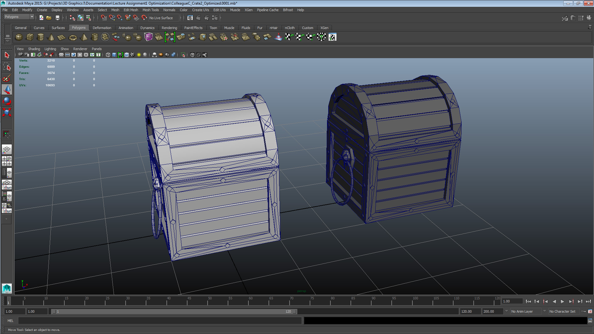
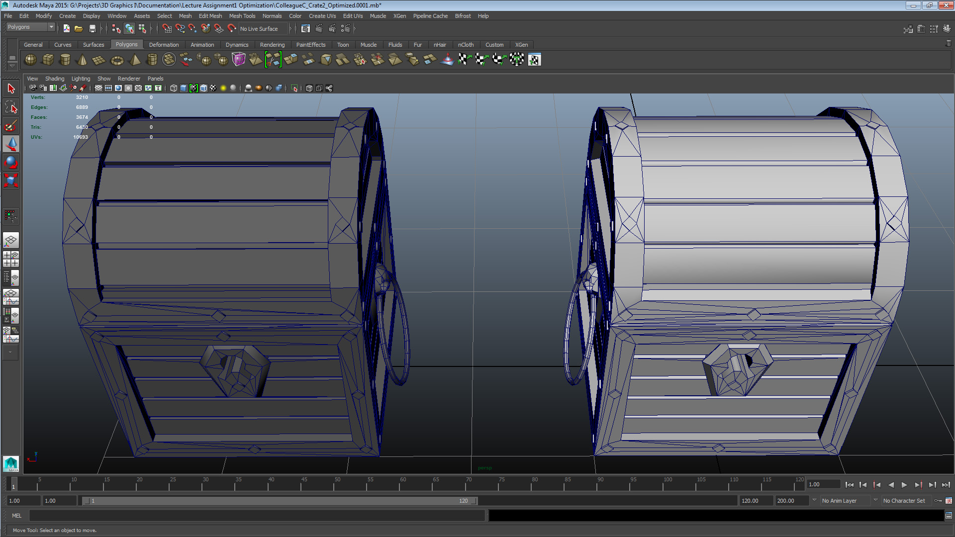
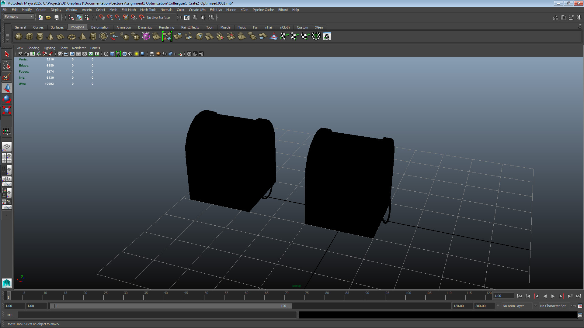
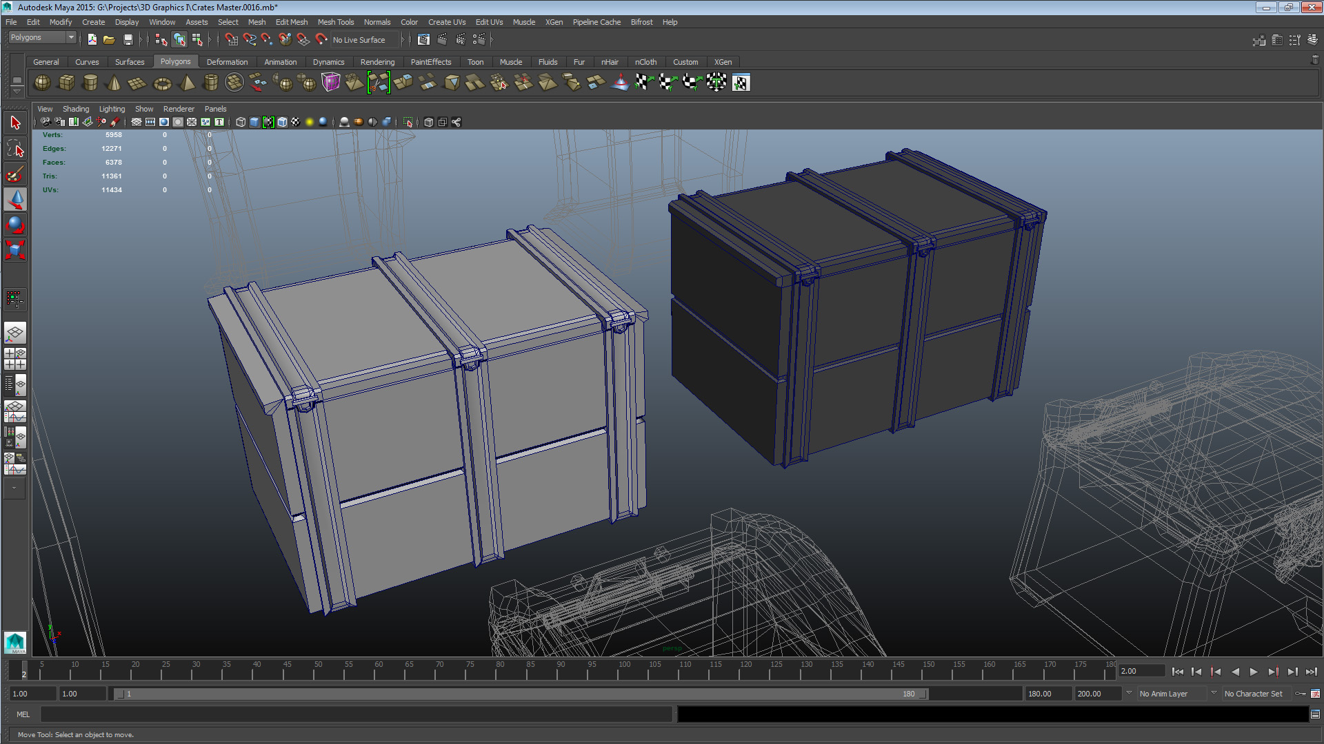
SET 2 CRATE COLLEAGUE C – CRATE 2 UNOPT: V 1680 E 3548 F 1866 TRI 3364 CRATE COLLEAGUE C – CRATE 2 OPT: V 1530 E 3341 F 1808 TRI 3066 This asset had issues primarily derived from a messy tessellation process during construction. I mainly focused on straightening out the edge flow, my goal was to make the mesh more workable. In addition to that, I saw an opportunity for effective geometry in the dividing extrudes all over the mesh, by splitting their central face in two and them merging the four controlling vertices into two. In addition to the issues with the automated nature of the geometry, there were also some construction oddities – such as that the extrudes were not in level with one another – that made things more complex. Ultimately I focused on making the edge flow more suitable for humans to work with, and saved some geometry in the extrudes and on cleaning up some left-over and unused geometry. After the lecture I realized I had made some faulty vertex merges, which I solved by deleting the resulting faces and reconstructing them from existing geometry in the affected area. The tip I gave to the authoring colleague was to consider when the added complexity of the mesh outweighs the value of having an element as an embedded element of the mesh as opposed to an external. Set 3 – Colleague B Crate 1
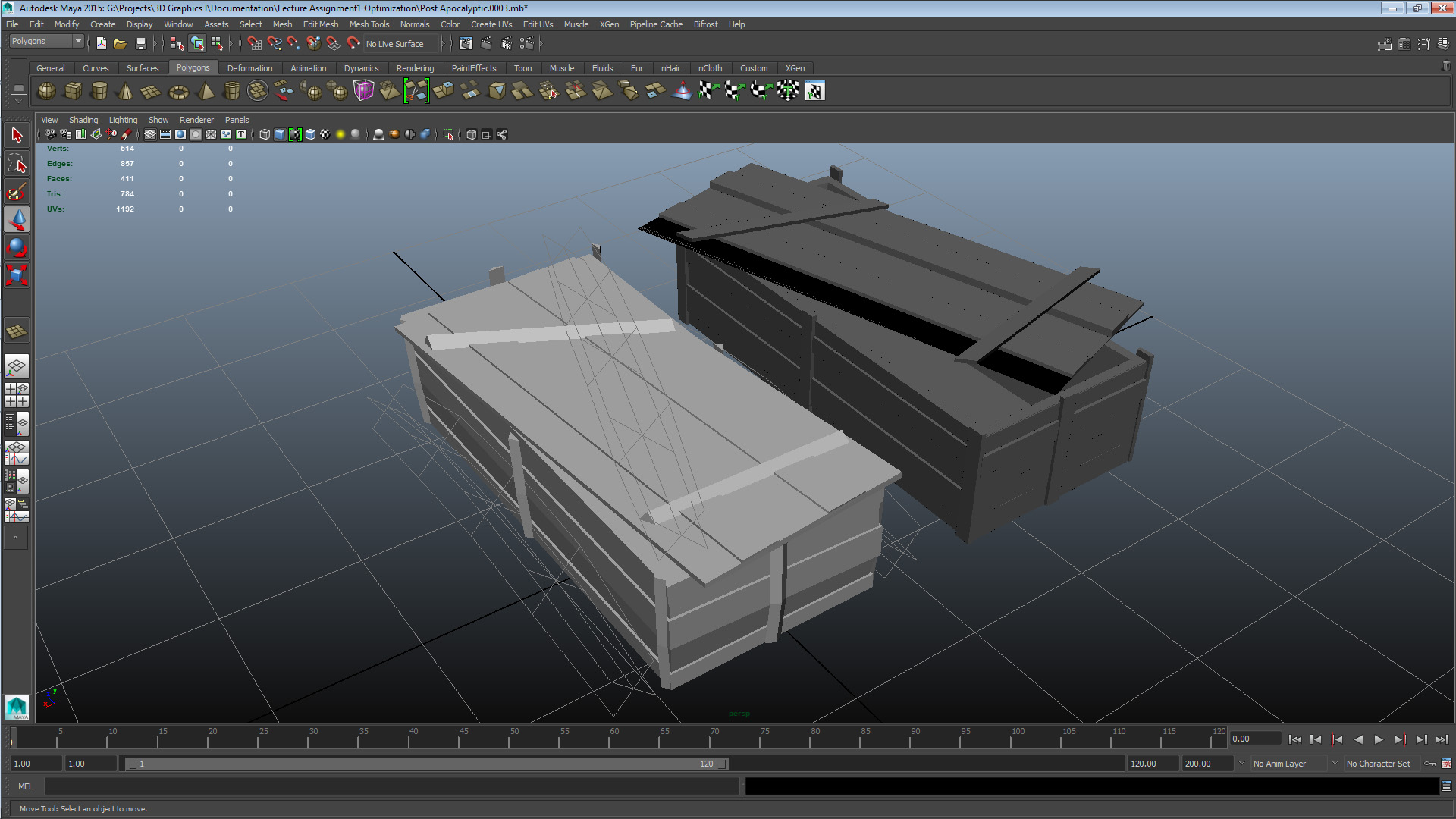
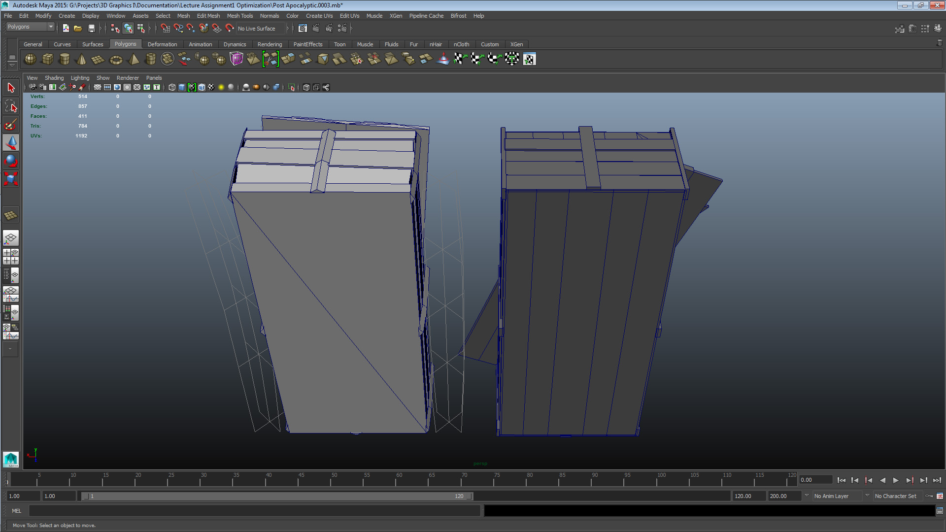
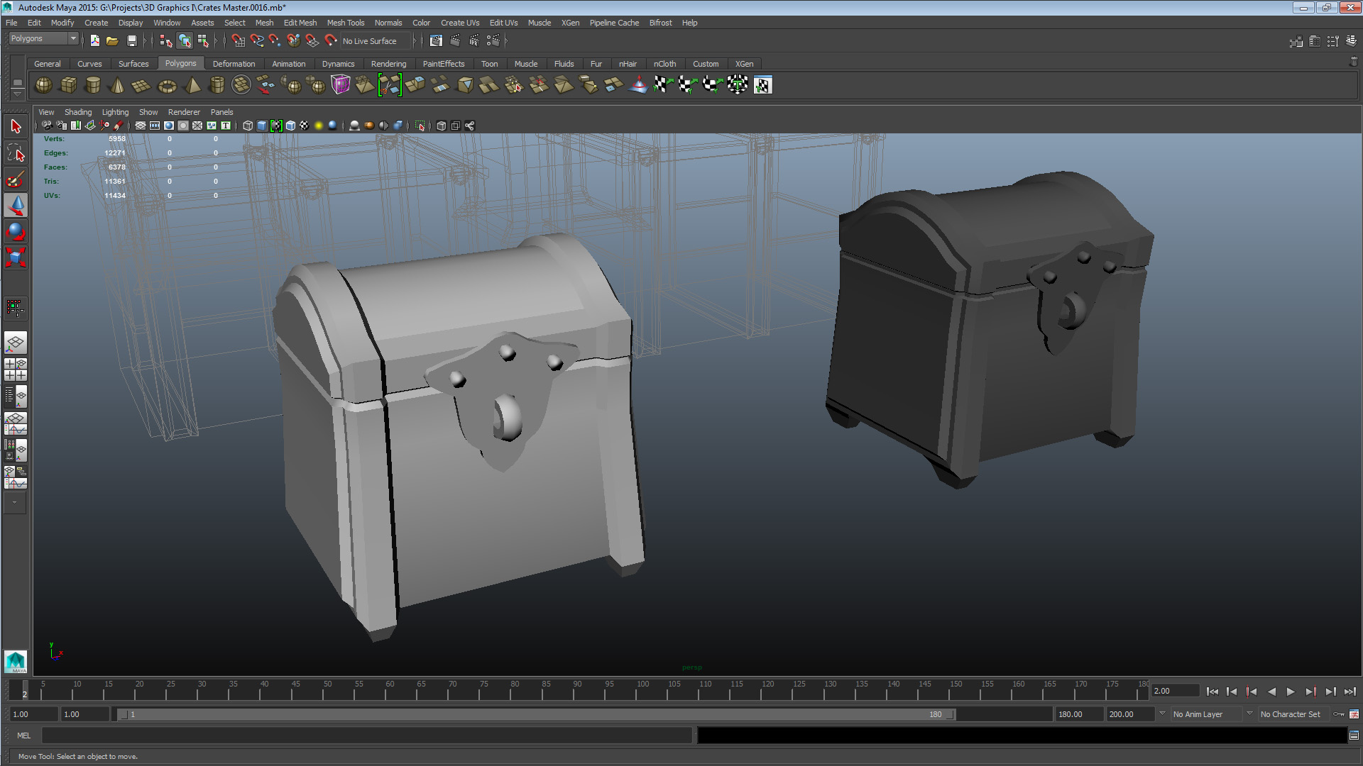
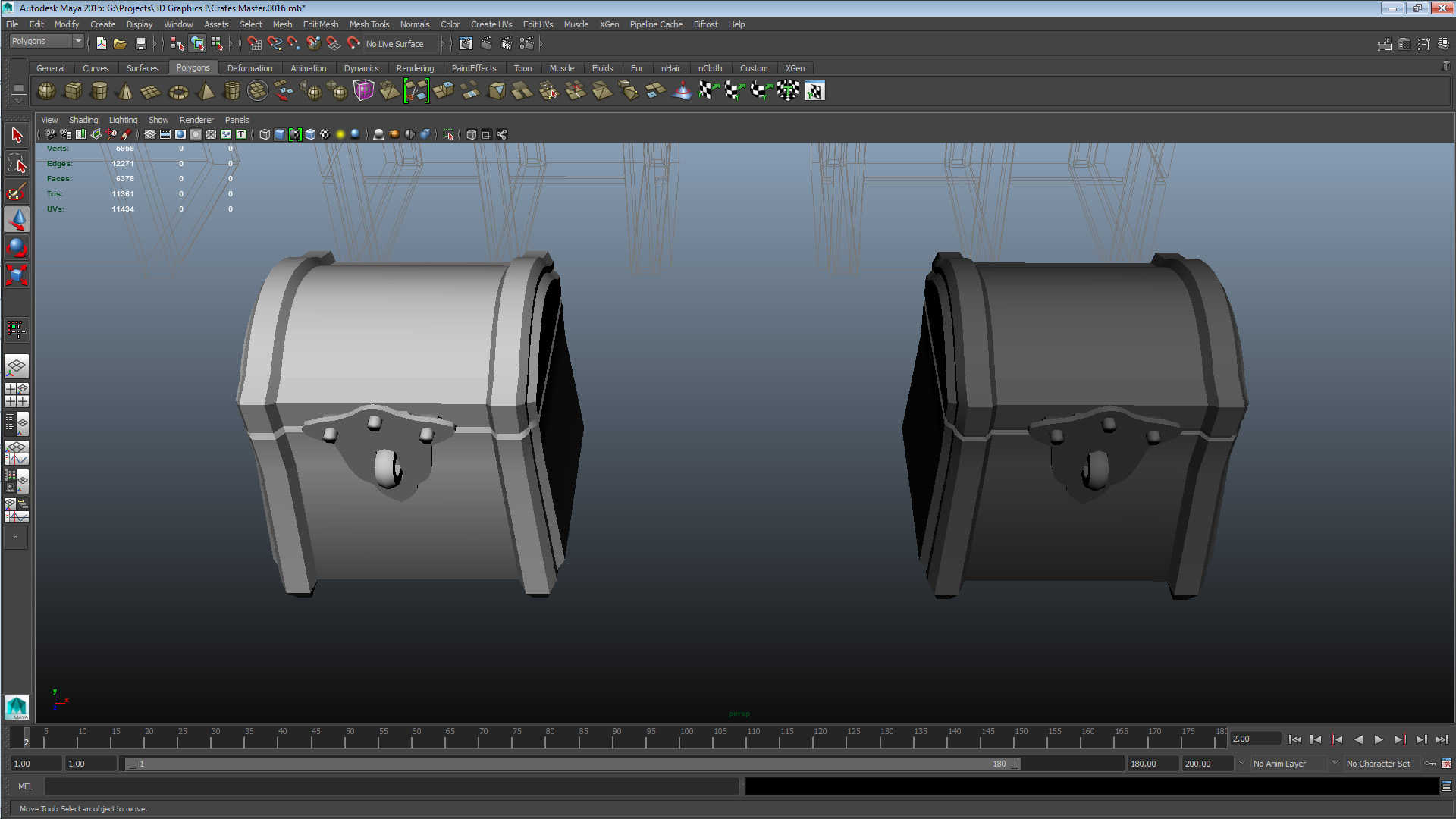
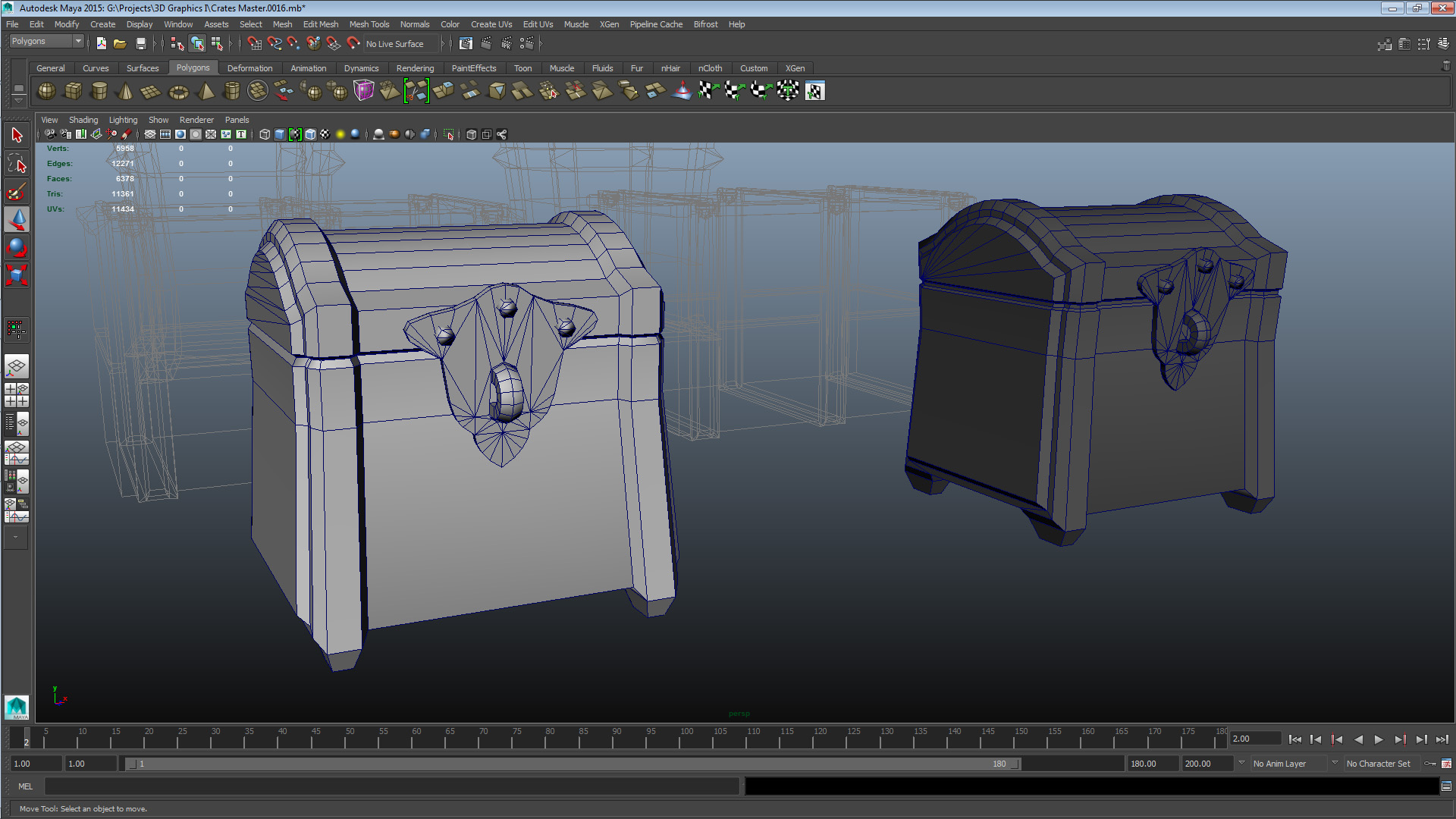
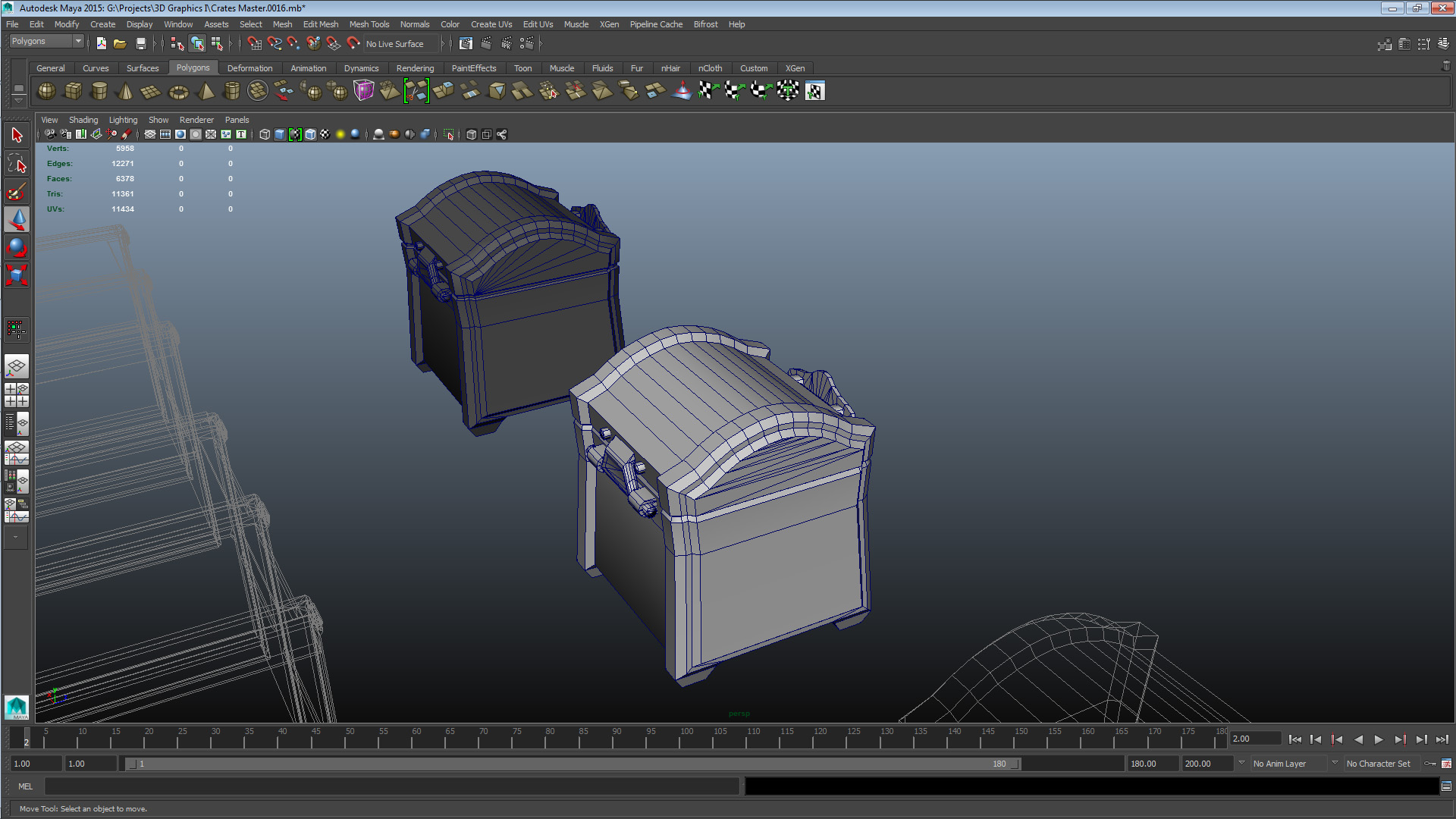
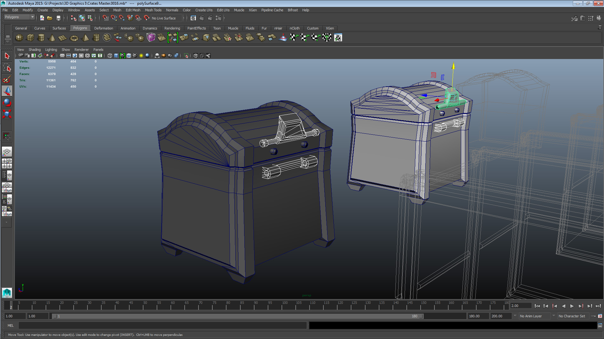
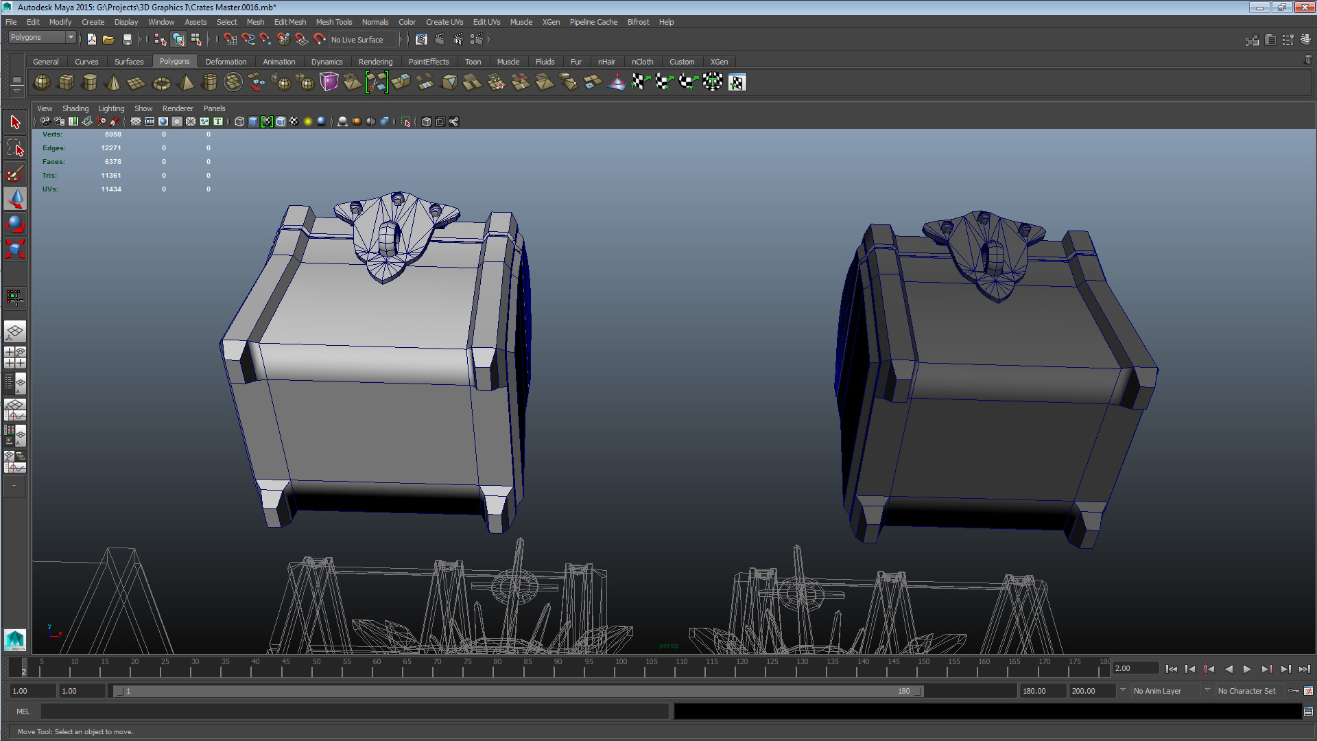
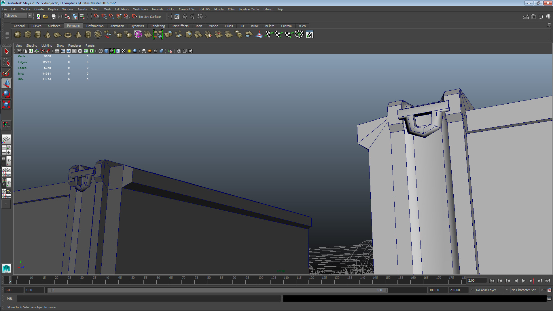
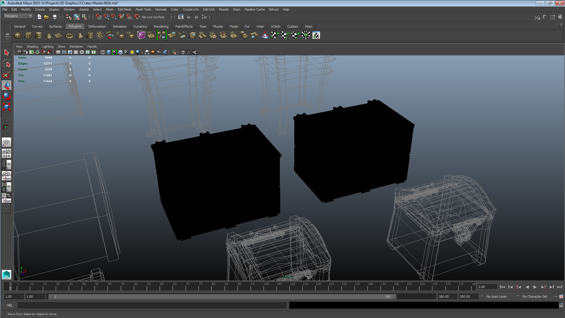
SET 3 CRATE 1 – UNOPT: V 969 E 2001 F 1041 TRI 1844 CRATE 1 – OPT: V 793 E 1699 F 919 TRI 1486 This crate had a number of issues, both conceptual and construction related. There were also some inefficient features derived from a lack of consideration about mesh application. I tried to resolve these issues by re-working some parts of the mesh completely (mainly the hinges and crate body top bevel) in order to configure them more resource-efficiently. There were also some features and decisions that would be an issue in the next phase of the model – unwrapping and texturing – that I tried to resolve. In summary, the mesh wasn’t very well planned out, and that’s what I had to try and deal with. When planning for the asset I should have considered where it would be used, and what kind of level of detail and ambition would be required for it to successfully be utilized in its context. Set 4 – Colleague B Crate 2
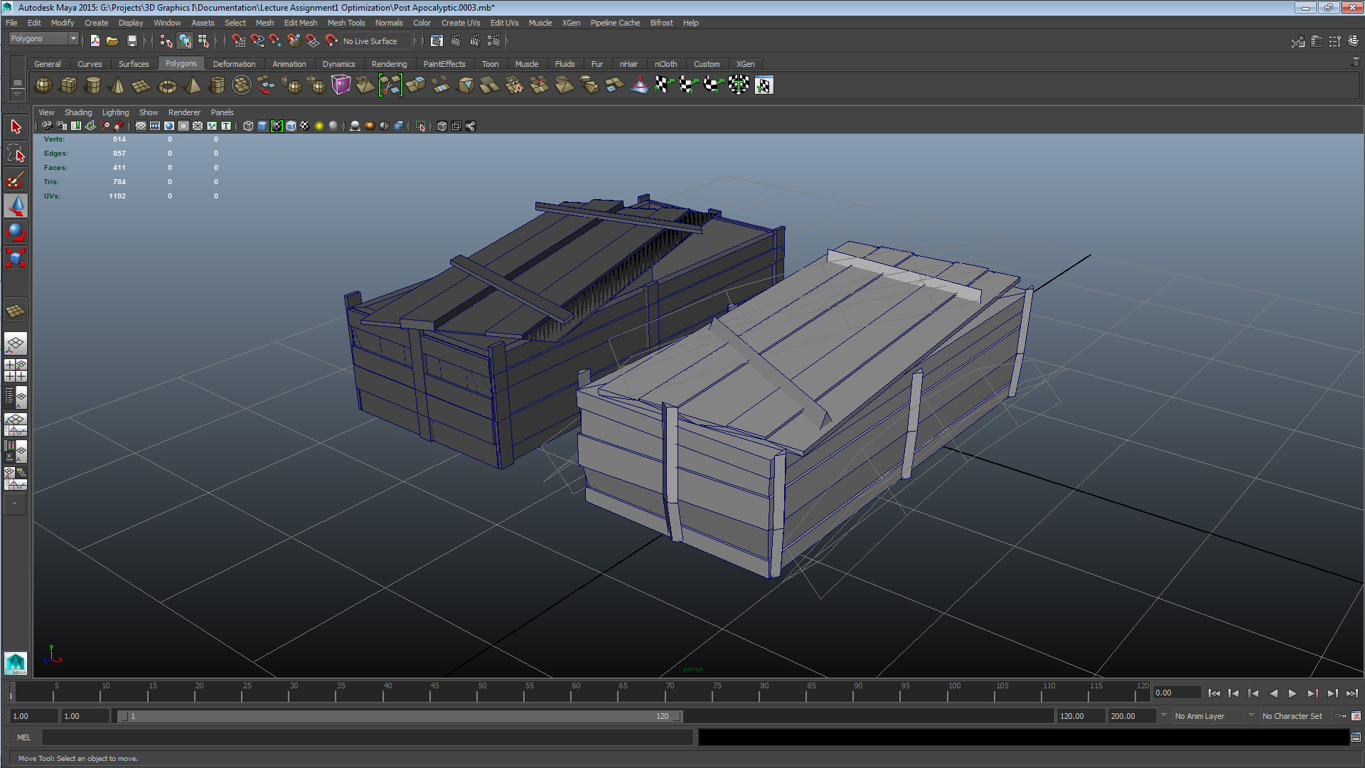
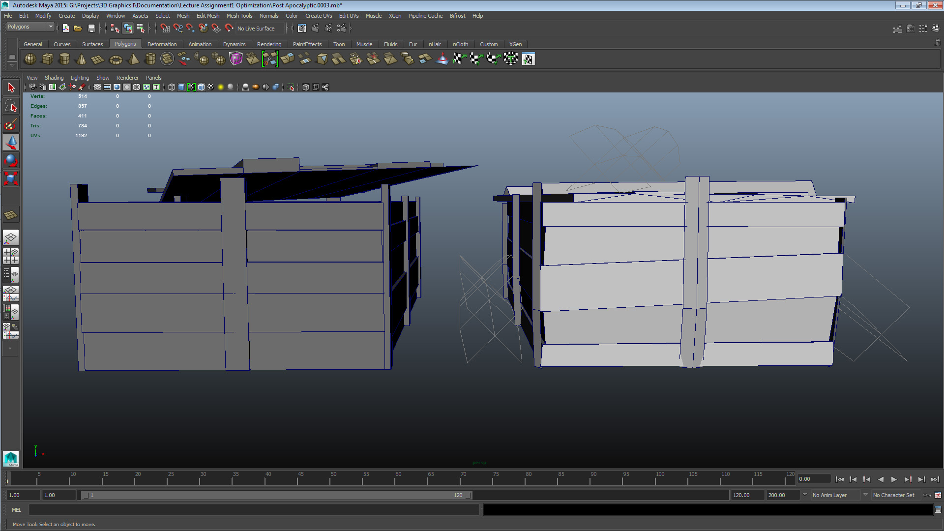
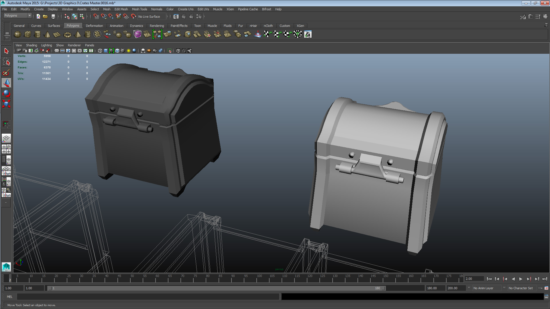
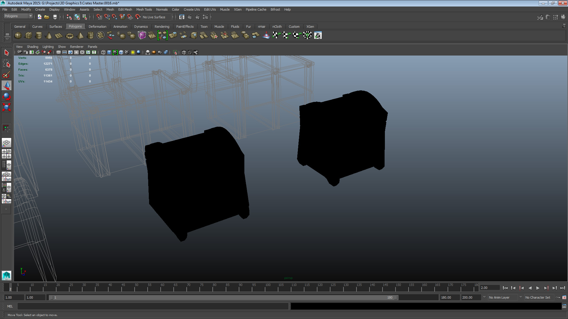
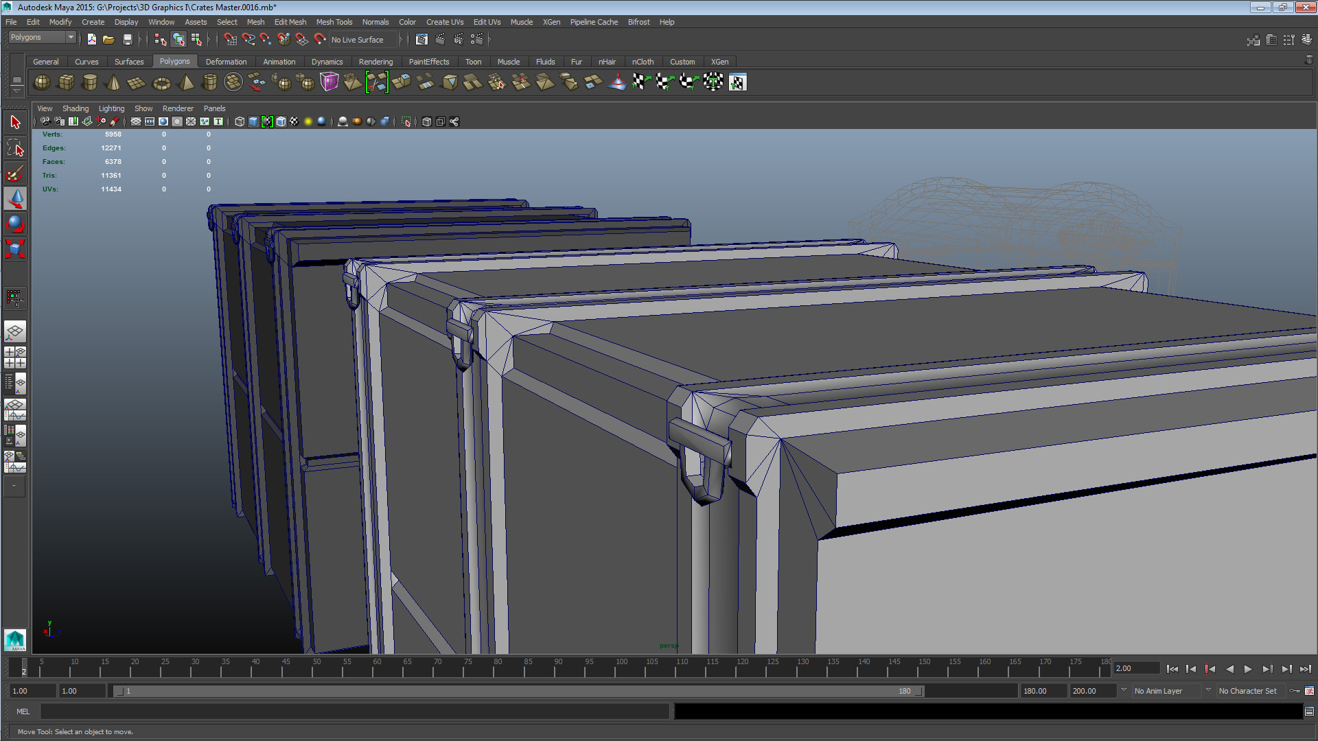
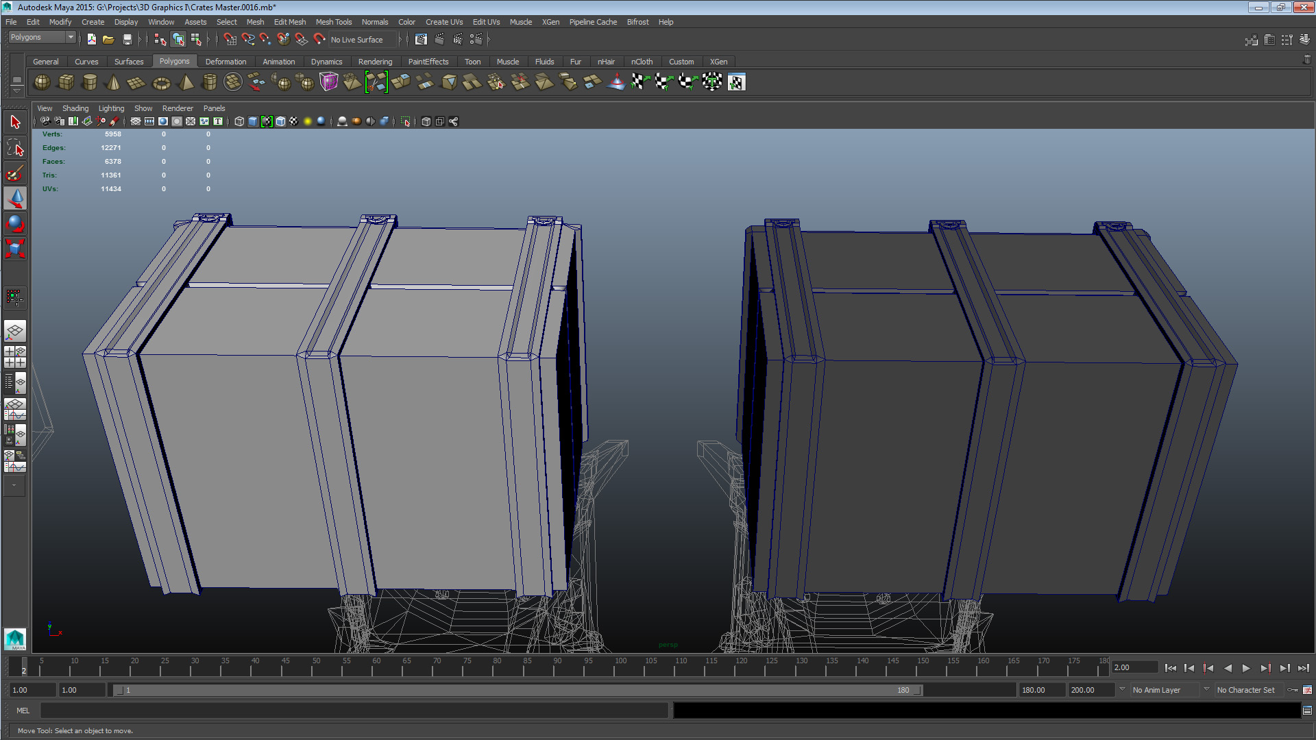
SET 4 CRATE 2 – UNOPT: V 639 E 1274 F 638 TRI 1272 CRATE 2 – OPT: V 558 E 1184 F 628 TRI 1112 This mesh is rather sparse on elements, but there were some opportunities to free up geometry. I focused on tracking down unused or underused vertices and merging them with their closest neighbour. Optimizing this crate was to summarize a straight-forward clean-up job. The most relevant issue with this crate was and still is conceptual inefficiency. The detail elements are too small to have any major impact on the silhouette of them mesh, and the rest is just too plain. Fixing these issues however did not fall within the scope of optimization so for this one I cleaned up what I could, and left the rest as it is. Set 5 – Colleague B Crate 3
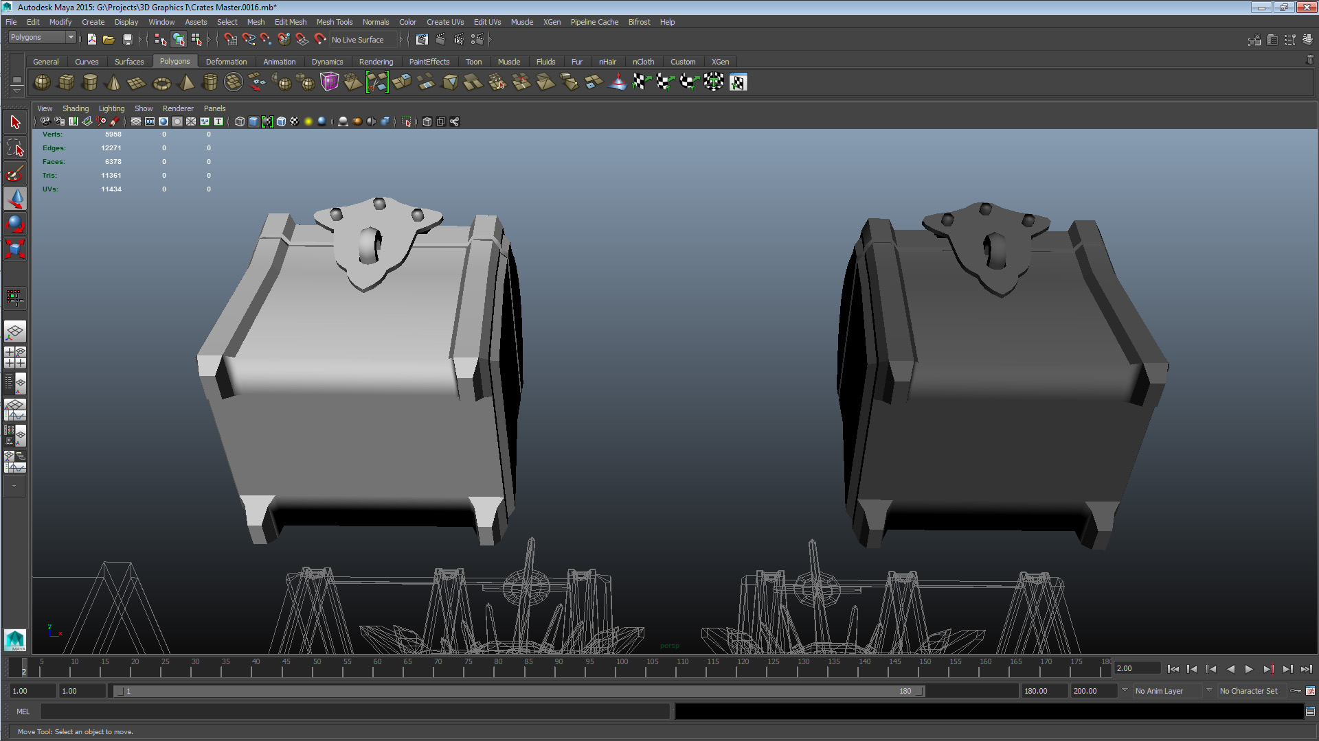
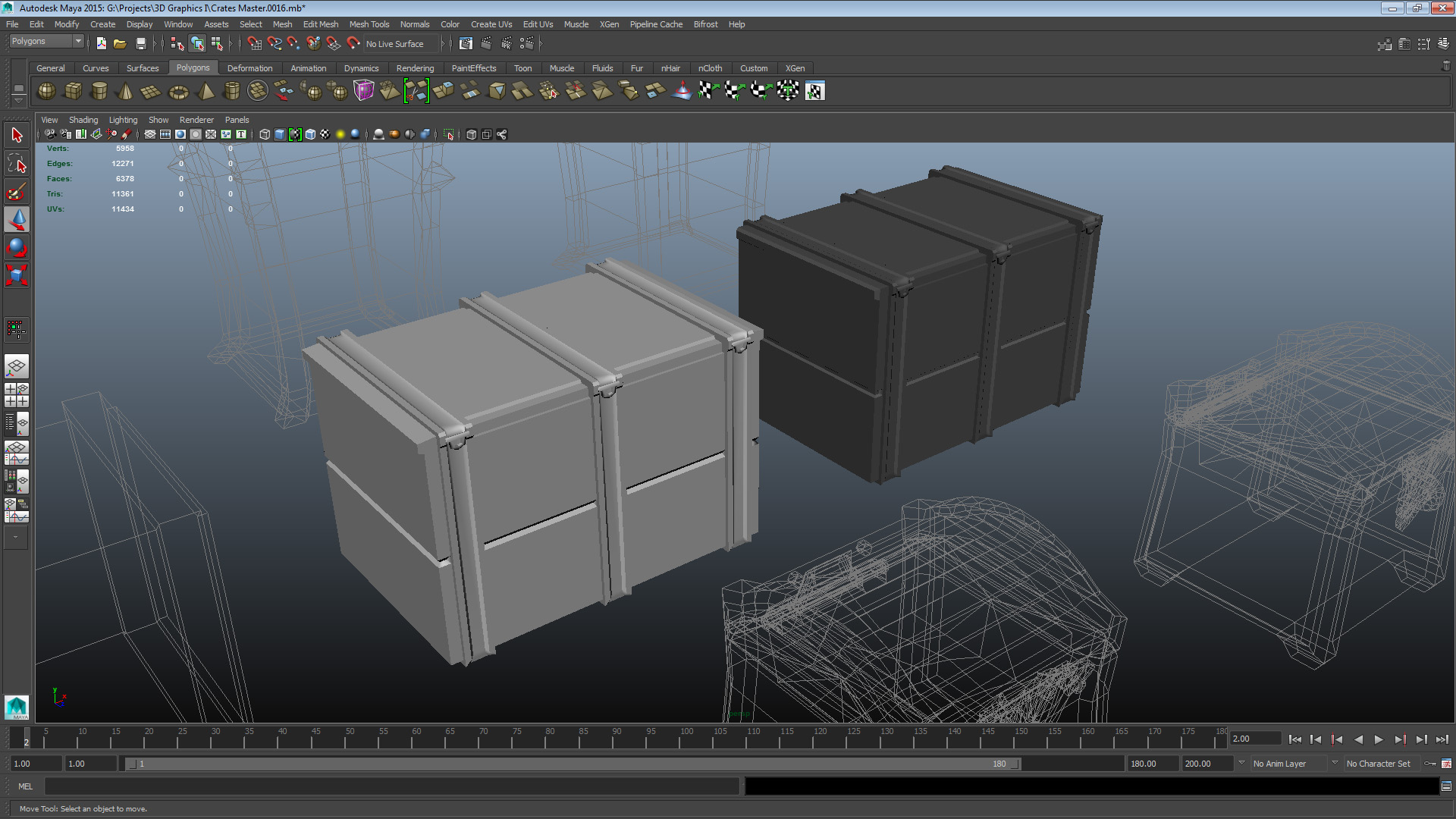
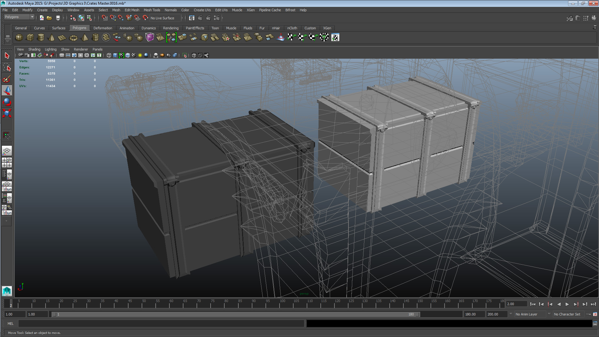
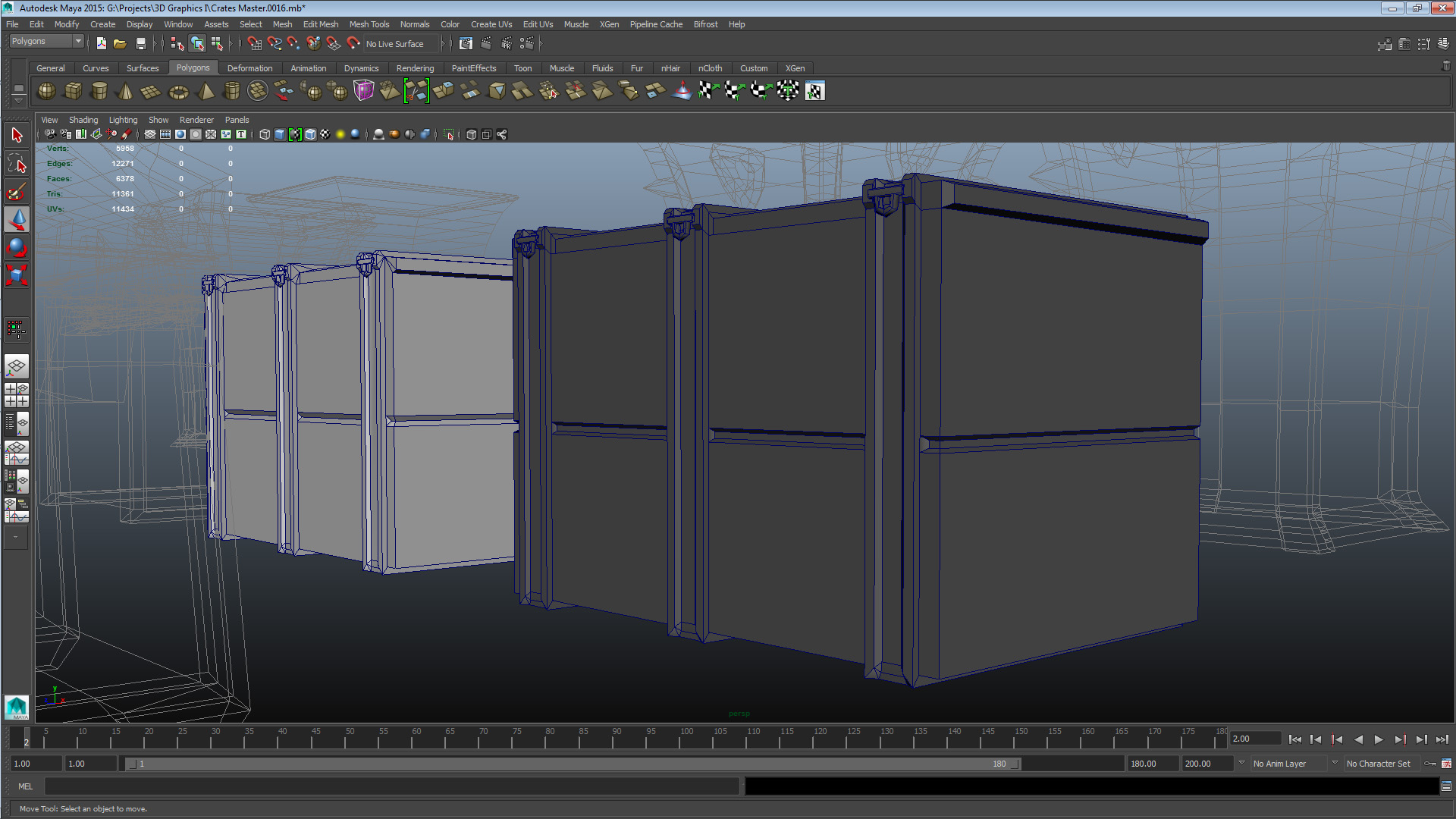
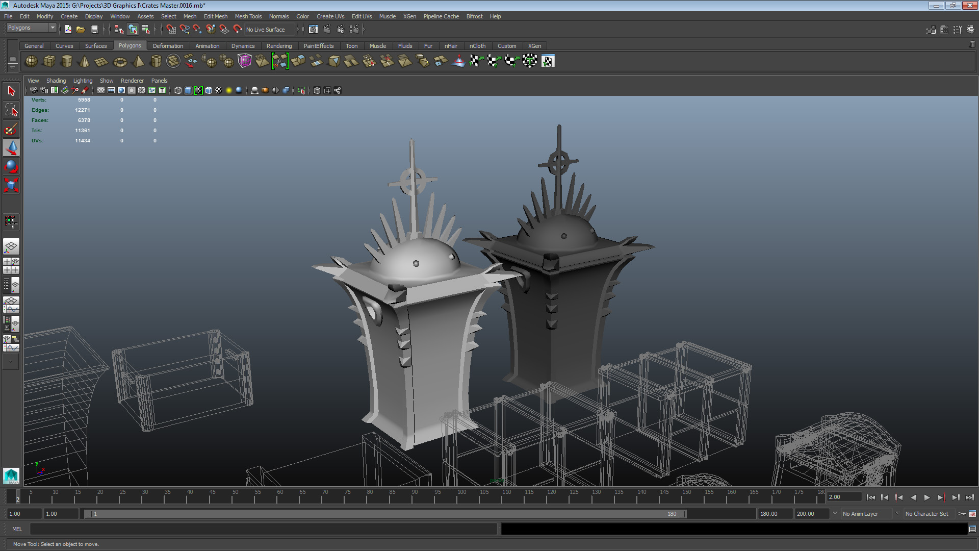
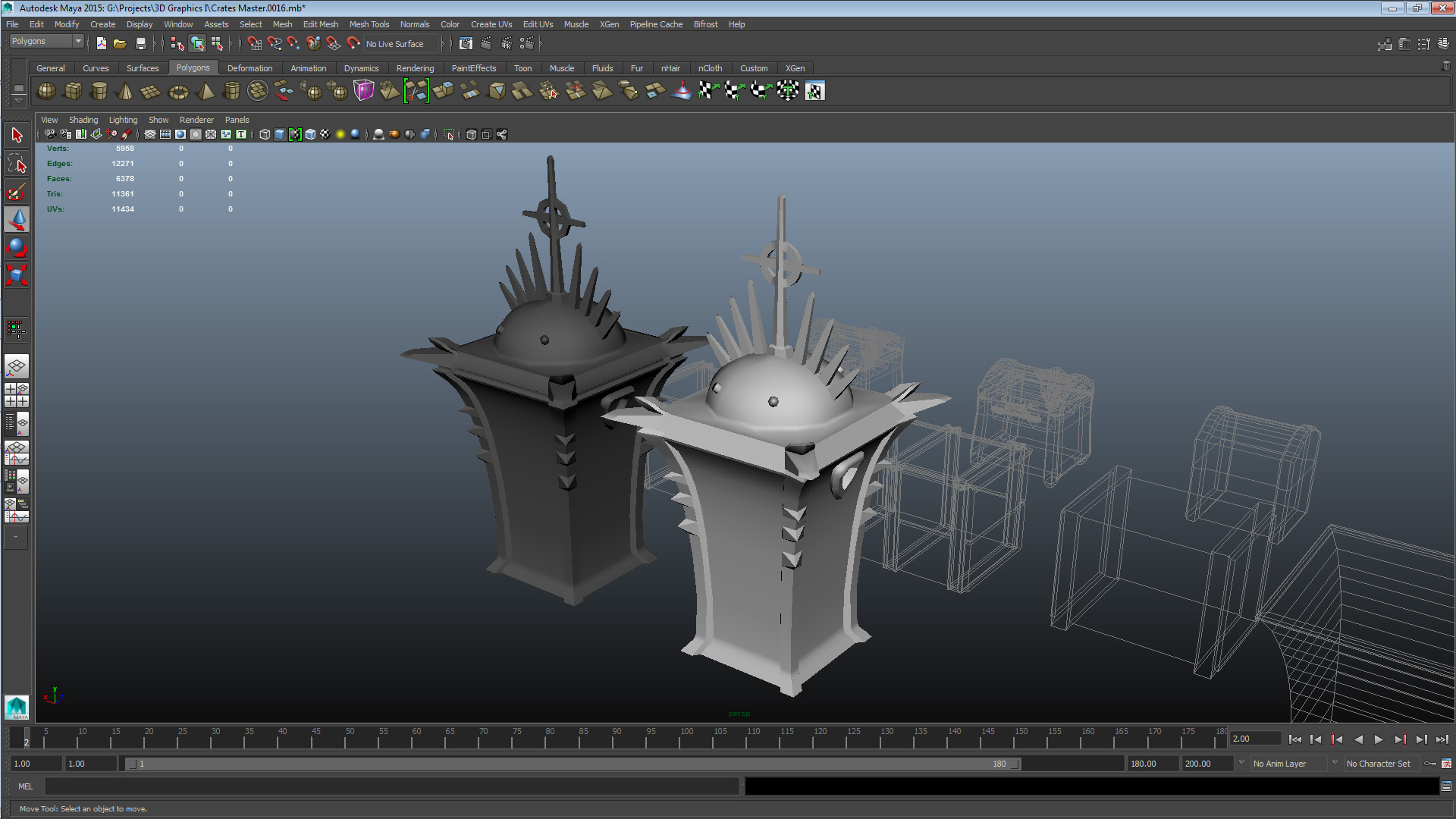
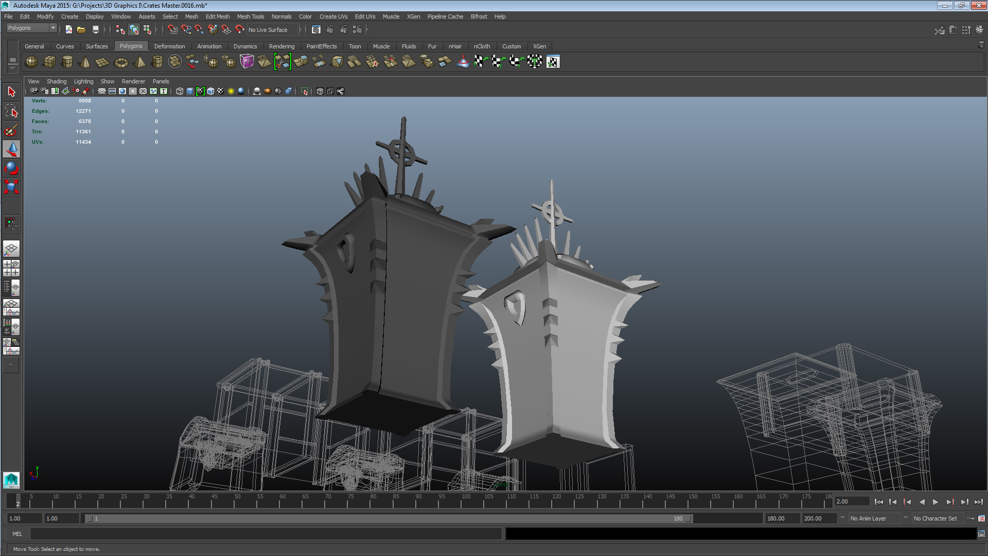
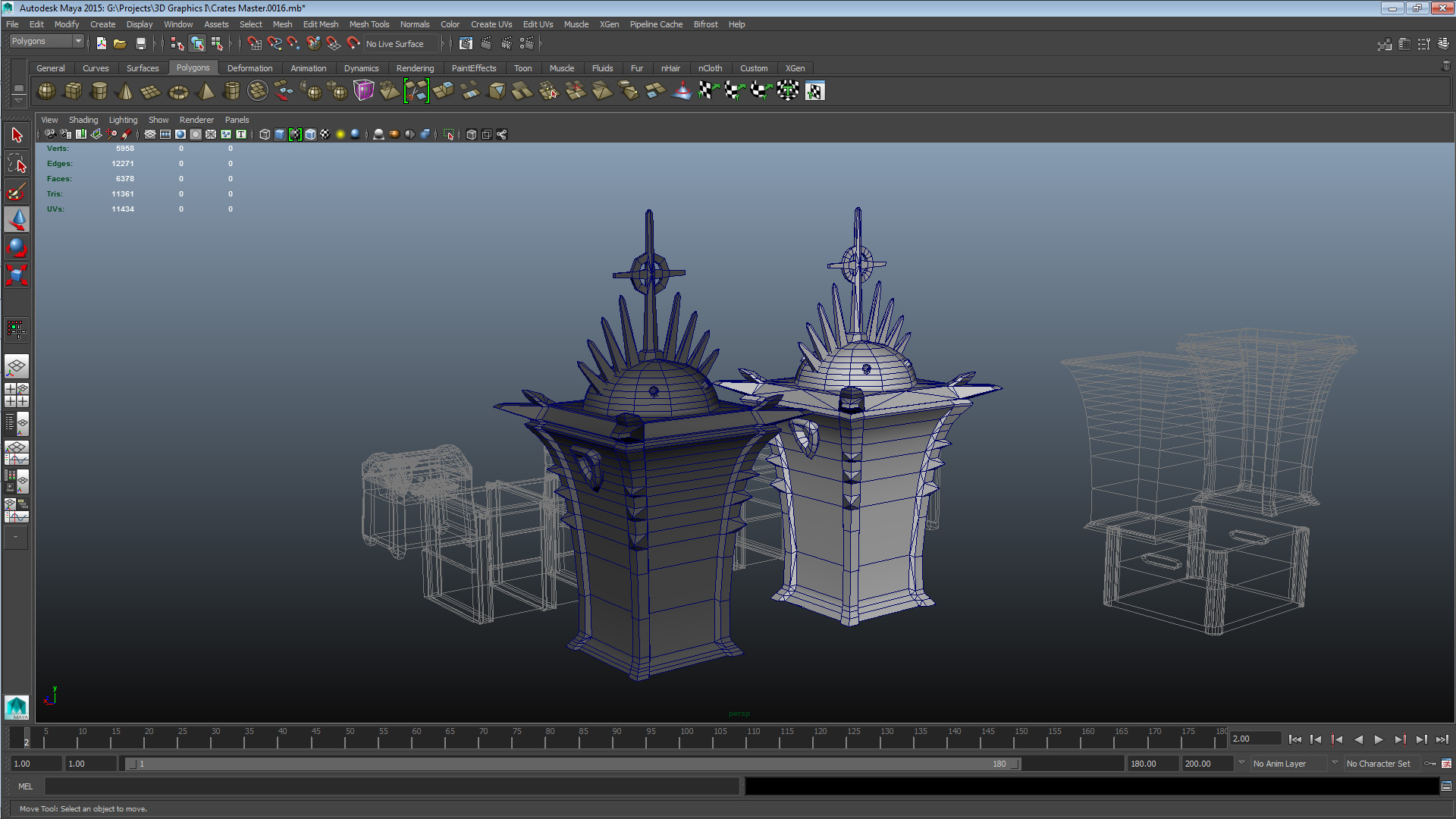
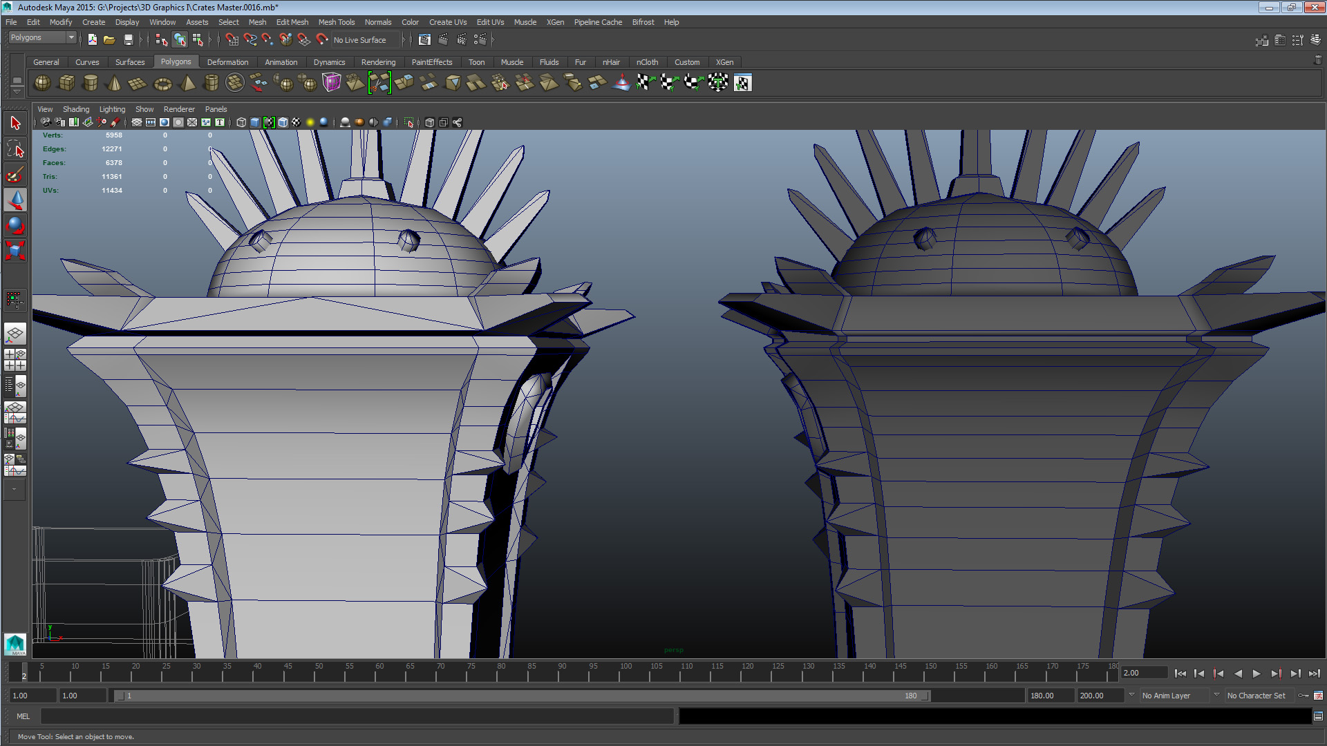
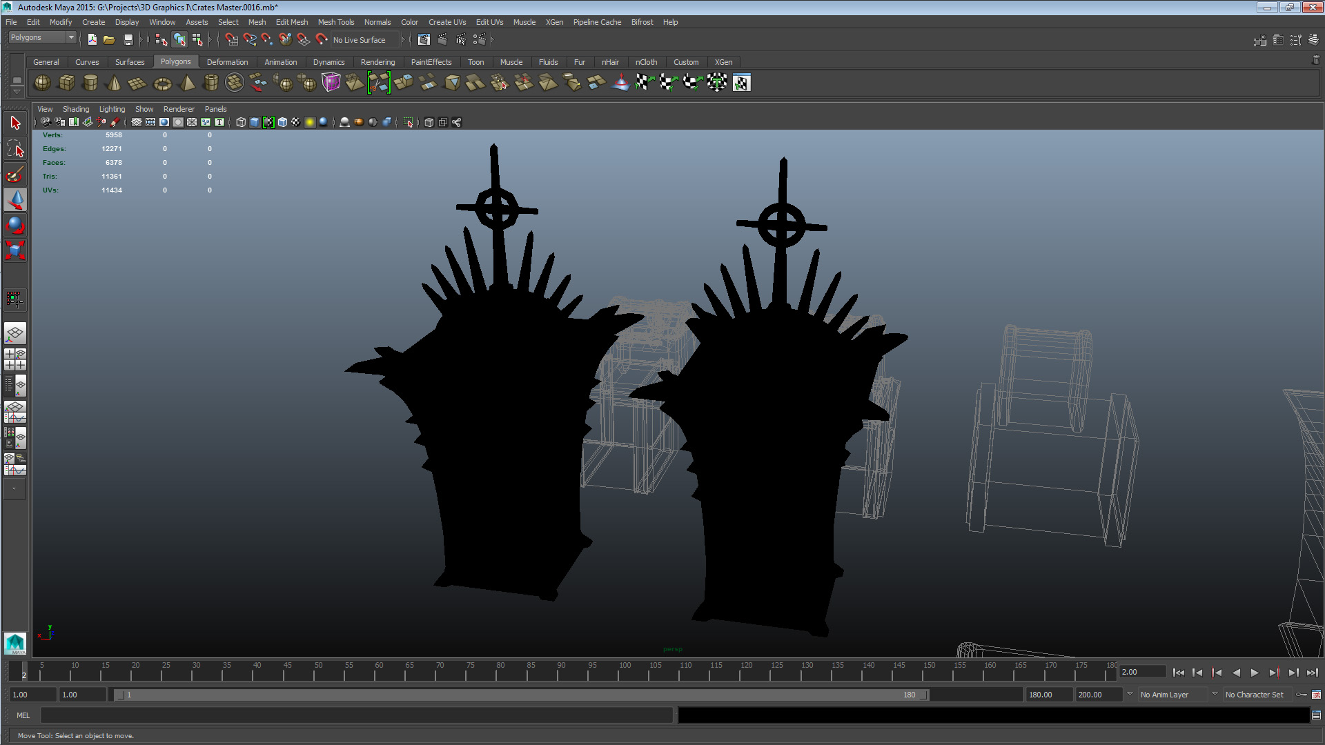
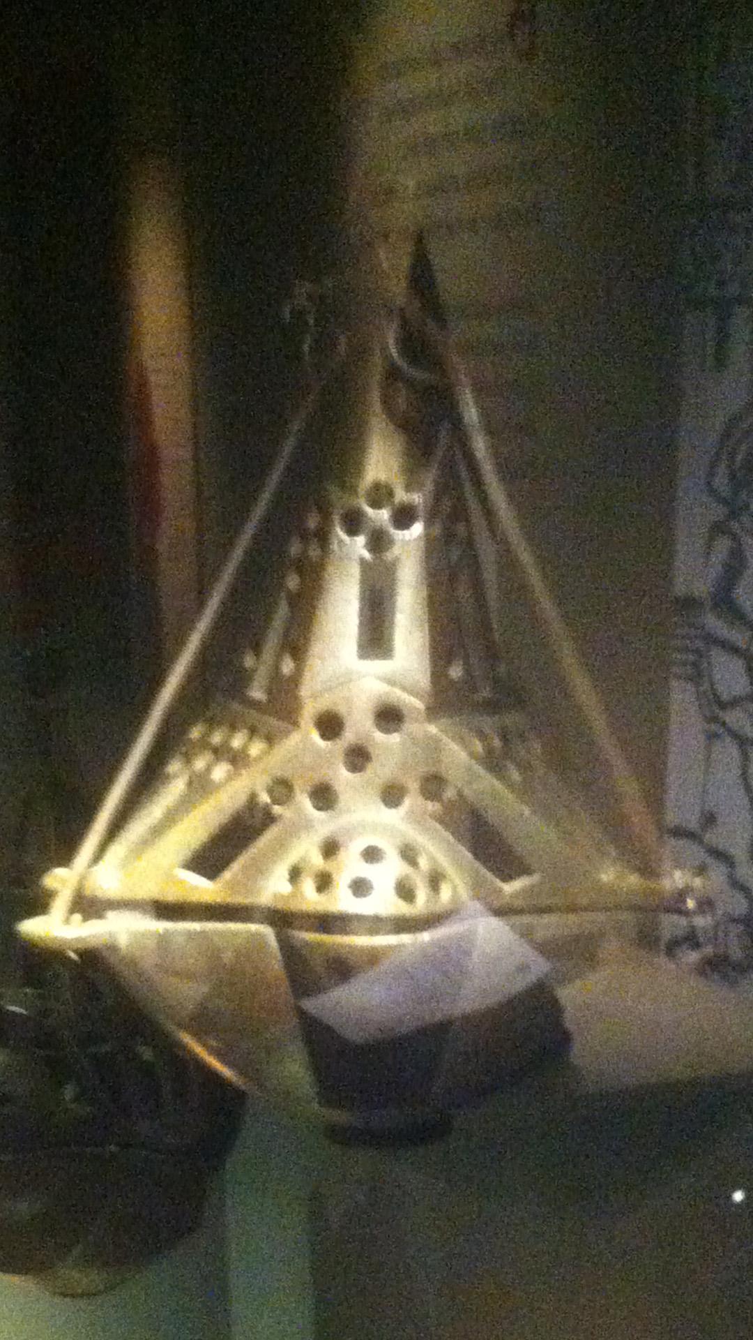
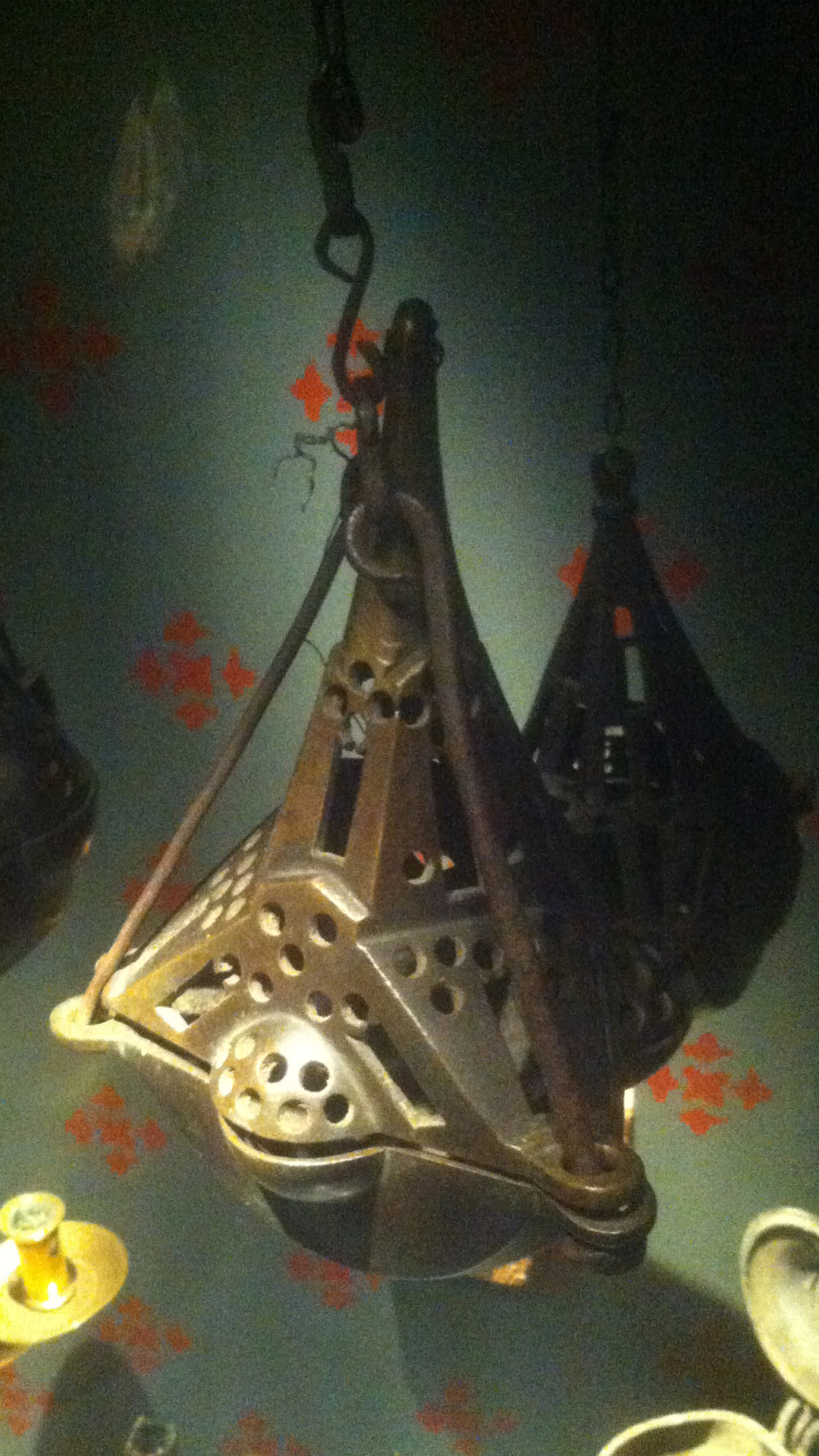
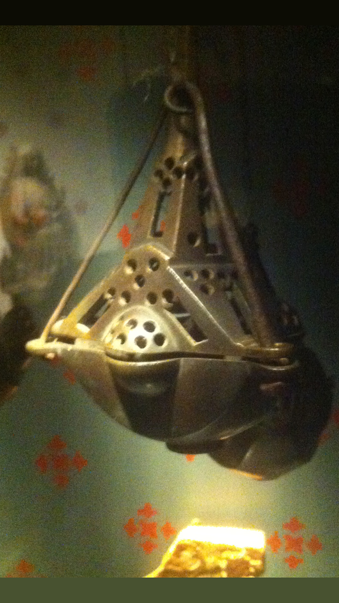
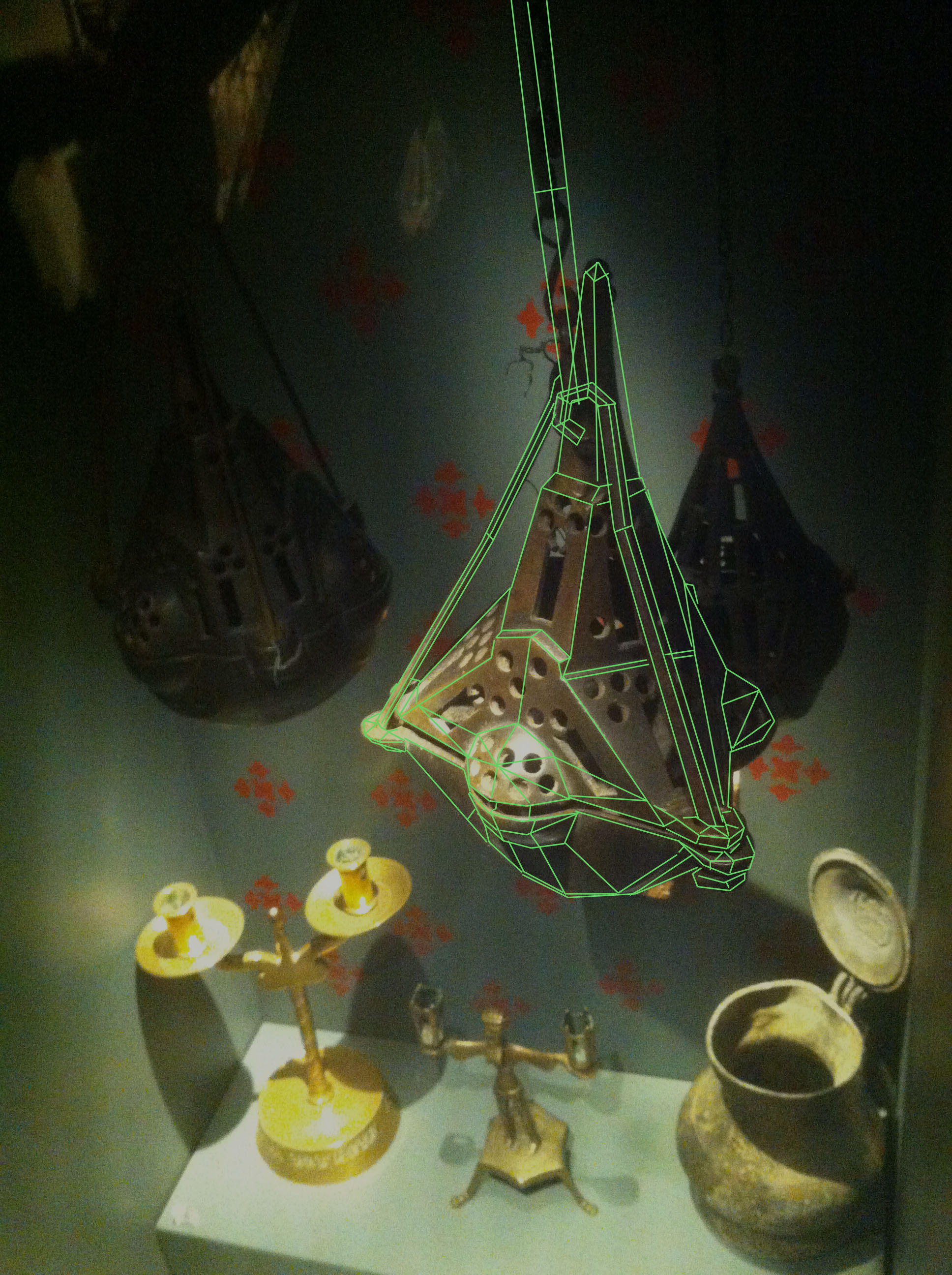
SET 5 CRATE 3 – UNOPT: V 1089 E 2154 F 1075 TRI 1914 CRATE 3 – OPT: V 880 E 1961 F 1055 TRI 1664 With this mesh I focused on rationalizing the design, removing and adding geometry where I figured it would be fit to improve the meshes usability. I also cleaned up unnecessary features and underused vertices. I’d reflect more on it but I’m already pushing the word limit and have not yet touched on the museum visit so I’ll let the pictures do the talking and move on. Now about the museum visit and the object reference I’ll be working with in the coming weeks. I chose a 14th century censer that was in one of the display cases. The censer was probably used in a religious context.
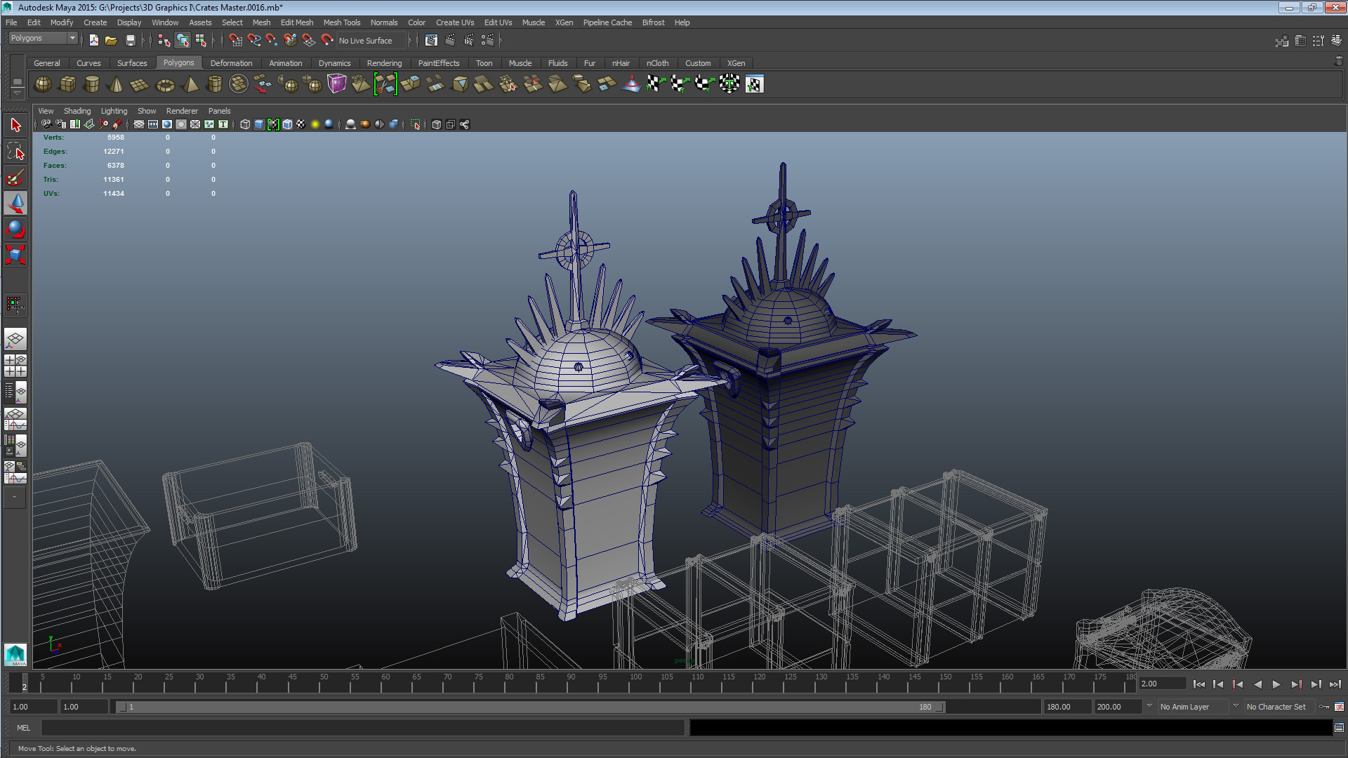
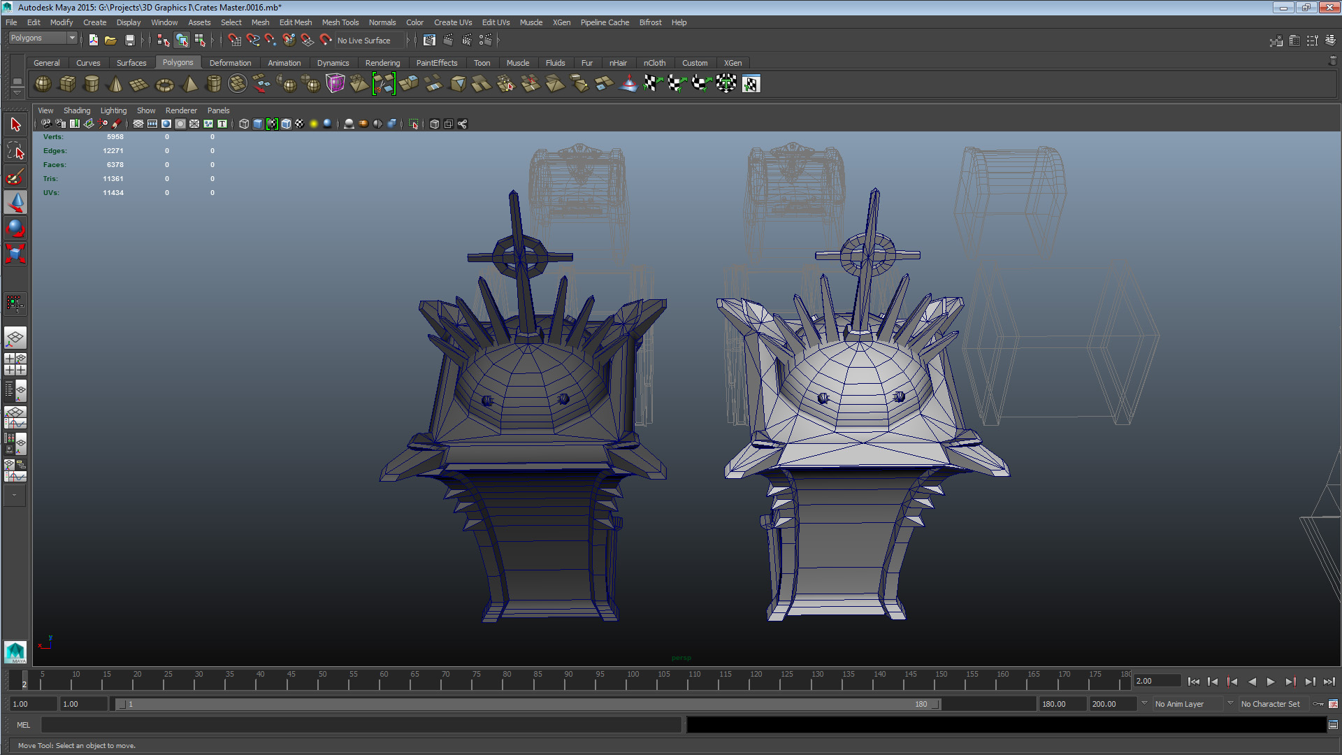
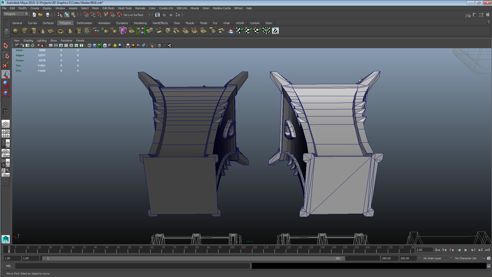
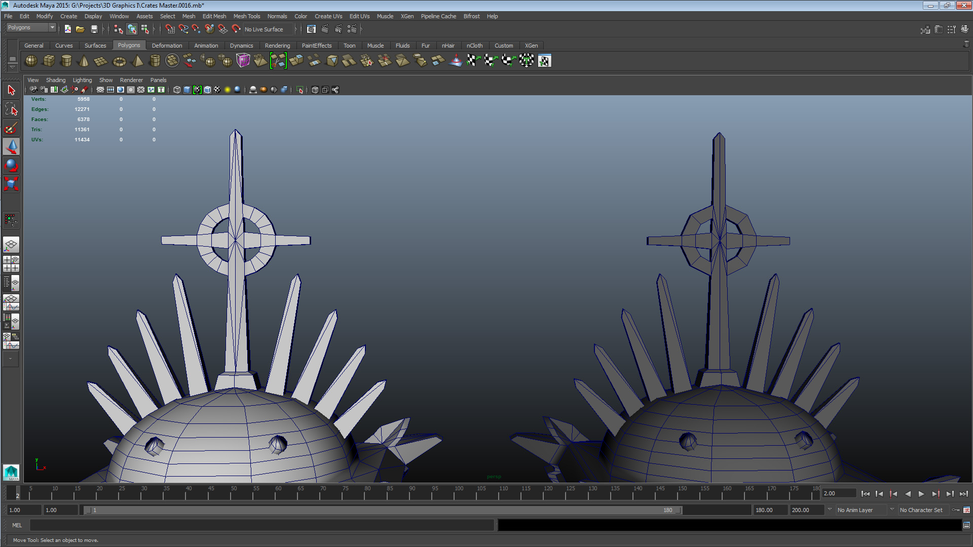
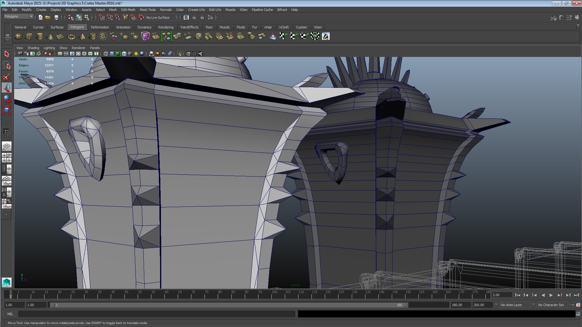
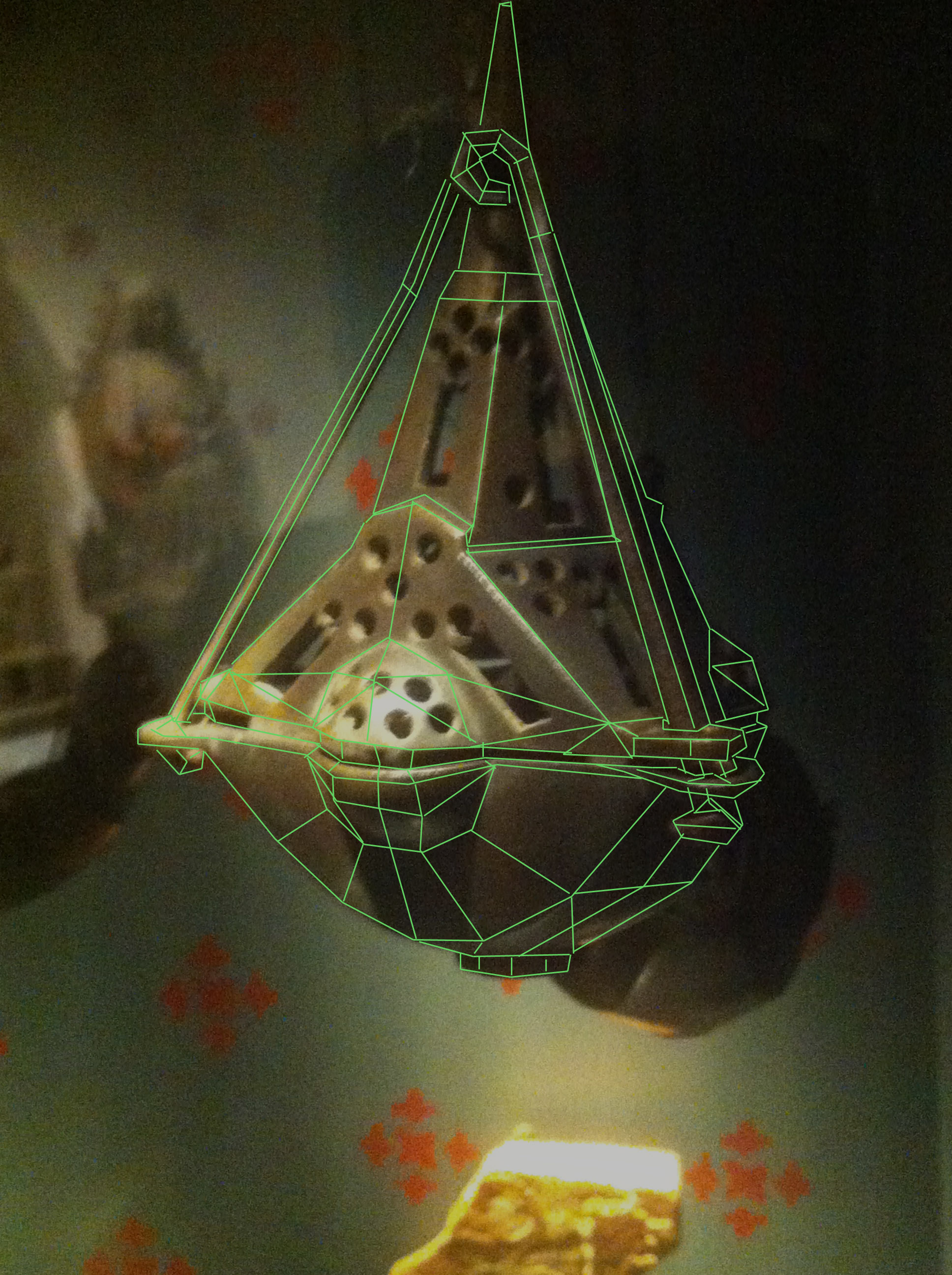
The style I’ll be modeling this in is the contemporary realistic style, which means that I’ll try to keep the object as authentic as possible within the frame of in what sort of a context an ornamental object like this would be used in a real-time environment. No matter how I go about applying the visual style to the object reference, there’s plenty of interesting geometry to contend with in this object, that’s why I decided to go with it after going through the entire exhibition. To not disregard the visual style here are my thoughts about how I’ll apply this mesh to the visual style; I will emphasize the hard angular surfaces and I will in turn tone down the embellishments. This because shape and form are the supposed principles behind Scandinavian design, and that is the positive stereotype I want to project. This is a positive stereotype for me to reinforce as I am attempting to convey the objects history with its visuals. The embellishments however, play into a potentially (in this particular case) negative stereotype with incensories which is their association with eastern cultures. I’ll also keep the texture work a bit darker than the reference to avoid any viewers mistaking it as gold or silver, which would reinforce the stereotype I’m hoping to avoid. The biggest risk I’m running during the development of this asset is that I might get to caught up in making a nice object and losing sight of what would make it a useful asset. I hope to avoid mesh hell by accomplishing the basic mesh shape as soon into the process as possible. In short, I’ll aim to “Keep It Simple, Stupid!”. Finally, two mockups of the edge flow:
That’s all for this post, peace out! |